Modern tantalum capacitors and supercapacitors make it possible for compact energy harvesting systems to power IoT MCU applications.
Ron Demcko, Daniel West, Ashley Stanziola • Kyocera AVX
Advanced tantalum capacitors and supercapacitors are enabling advanced ICs to be powered by compact and low-cost energy harvesting and scavenging sources. These developments make possible maintenance-free control systems in IoT applications extending from remote monitoring to smart industrial point controllers, wearable electronics, and location tracking devices.
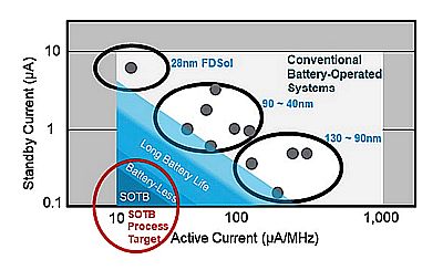
Consider as a case in point the RE family of Renesas MCUs. It is based on the company’s silicon-on-thin-buried-oxide (SoTB) process technology which enables ultra-low power consumption in both active and standby modes. RE family MCUs typically consume 25 µA/MHz when active in internal low-dropout regulator (LDO) mode, 12 µA/MHz in external dc/dc mode, 400 nA in standby with 32 KB RAM retention, and 100 nA in deep standby. Low current consumption at low voltages allows these advanced MCUs to employ energy harvesting or scavenging power sources rather than traditional batteries or mains.
Each RE01 MCU contains an energy harvesting controller (EHC) equipped with a sub-level PMIC, charge controller, and power management function. These EHCs harvest energy generated from solar, piezoelectric, micro turbine, pressure, and thermal electric generator (TEG) power sources. The MCUs use one of two integrated capacitors to manage, channel, and balance harvested power and MCU power consumption. In this application, the EHCs provide basic functions like reverse-current protection and also act as the direct energy harvesting link. The energy harvesting actions include voltage regulation, quick start-up control, autonomous and reliable start-up sequencing, start-up current control, energy storage charge management, and the selection of capacitor power sources.
When an RE01 MCU is powered by harvested energy, an advanced tantalum capacitor provides temporary energy storage while a large-valued supercapacitor handles secondary storage. The ultra-low-power MCUs enabled by these advanced capacitors handle control and communication capabilities in IoT applications ranging from remote environmental monitoring and agricultural optimization to asset tracking, wearable electronics, and set-it-and-forget-it industrial monitoring.
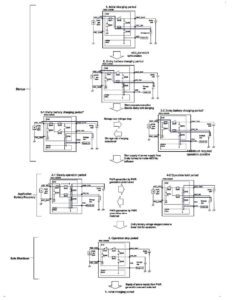
The EHCs in RE01 MCUs configured for energy harvesting rely on a start-up capacitor (C-SU) to charge quickly and to provide the low-level power for MCU power-up initiation. For long-term power, they can use batteries or advanced supercapacitors. Once energy harvesting power is apparent, the EHC charges the C-SU. When C-SU charges to 3.0 V, power-on reset initiates at the MCU and the secondary supercapacitor starts charging.
While the supercapacitor charges, the EHC uses C-SU power to initiate various MCU operations. Once the supercapacitor has charged, the MCU draws on its energy for longer-term operation. During that time, the C-SU recharges so it can maintain various active computing functions when the EHCs isolate the supercapacitors from the MCU to recharge them. Once the supercapacitors recharge, the MCU again transitions from the C-SU to the supercapacitor power source and, in doing so, enables more of its functions.
This process continues in a loop until the energy harvesting power source is no longer available and the system shuts down. At that point, the MCU waits for C-SU to charge and the use cycle continues.
The start-up capacitor
The C-SU in an energy harvesting MCU must operate from -40 to + 85°C and provide 100–150 µF of capacitance across that temperature range. It also must exhibit low ESR (equivalent series resistance) during charging and low leakage current, or high insulation resistance, to reduce standby currents.
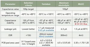
Three different capacitor technologies can exhibit these properties at around 3 V: tantalum, aluminum electrolytic, and multilayer ceramic capacitor (MLCC). Tantalum capacitors best meet the requirements of a start-up charge retention capacitor. Tantalum capacitors have stable values regardless of dc bias, operating temperature, or age. In contrast, an MLCC rated for 100 µF is likely to only demonstrate 20–30 µF in an application. High-capacitance MLCCs also come in packages larger than equivalent tantalum devices and exhibit extreme capacitance instability. Thus they aren’t recommended for use as start-up capacitors.
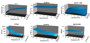
Aluminum electrolytic capacitors are more stable than MLCCs but at the price of increased size and weight and potentially much less reliability. Aluminum electrolytic capacitors squeeze large capacitance values into small packages, but their electrical properties vary with temperature.
Tantalum capacitors are available in numerous case styles, including true EIA case size surface-mount technology (SMT) chips and high-density under-tab styles. They also allow design engineers to further reduce any in-circuit leakage by derating the capacitor voltage rating.
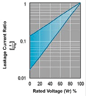
Consider as an example the KYOCERA AVX TPS Series tantalum capacitor (P/N: TPSC107K010R0200). TPS Series capacitors are automotive-grade components qualified to AEC-Q200 and available in 14 different case sizes (EIA 1206 to EIA 2917) with voltage ratings spanning 2.5–50 V and capacitance values extending from 0.15 µF to 1,500 µF. They exhibit ESR as low as 80 mΩ, a maximum direct leakage current of 19.8 μA, and a 12% maximum dissipation factor at 120 Hz. They are also rated for operating temperatures from -55 to +125°C and are suitable for battery support and smoothing/filtering on the 3.3-V power rails frequently chosen for dc/dc converter output voltage.
Supercapacitor selection
Supercapacitors (C-Bulk) are widely employed as low-cost alternatives to rechargeable batteries in applications requiring up to around a million charge/discharge cycles. Supercapacitor cycling qualities are well suited for high-frequency charge/discharge applications like energy harvesting MCUs. Supercapacitors are available in multiple form factors, simplifying their integration into a wide variety of end systems. Selection is generally based on a combination of package qualities and the application run time.

Consider two examples. In the first, two discrete, ultraminiature KYOCERA AVX SCC Series radial-can supercapacitors (P/N: SCCQ12B105PRB) connect in series to create a 0.5-F, 5.4-V storage device. The second example uses a miniature KYOCERA AVX SCM Series supercapacitor module (P/N: SCMR18C105PRBA0) comprised of two packaged, series-connected radial supercapacitors and rated for 1 F at 5V.
Radial-can supercapacitors are commonly used in single configurations for lower voltage designs, but multiple cans can be configured to handle higher voltage loads, as is the case in this study.
Multiple cans can be balanced via active or passive methods. Supercapacitor balancing is necessary to ensure long lifetimes for multiple supercapacitors connected in series. Balancing prevents any overvoltage on one capacitor from damaging any of the other supercapacitors in the stack. Passive balancing uses just a resistor and is the cheapest, smallest, and most user-friendly method. But it also comes with a disadvantage: Power dissipated through the balancing resistor reduces overall efficiency. Active semiconductor balancing is the most efficient and exacting method. However, it’s also more costly. The space required for active balancing varies greatly based upon the number of cells and the size of the semiconductors that do the balancing.
The RE MCU example uses SCC Series discrete radial-can supercapacitors. These devices come in 10 different case sizes rated for 2.7 V from -40 to +65°C and 2.3 V from -40 to +85°C. The SCC Series also spans capacitance values of 1–3,000 F, giving designers a high degree of flexibility. Competing solutions are also readily available.
Modular radial-can packages are manufactured by connecting two radial-can supercapacitors in series and packaging them as a module. This approach packs more capacitance into a given package size and enables higher voltage ratings. These modules can be balanced or unbalanced and feature hard-shell or heat-shrink packaging depending on the application reliability requirements.
SCM Series supercapacitor modules have a much larger storage capacitance than the SCC Series and, as such, can power the MCU load for an extending period of time.
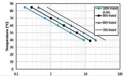
Regardless of the specific package configuration, supercapacitors must be derated for reliable long-term operation. Studies have revealed that supercapacitor reliability is a function of applied voltage and operating temperature. In tests, various acetonitrile (ACN) chemistry supercapacitors underwent matrix testing with varied voltage, temperature, and humidity stress levels. Researchers measured the capacitance and ESR of the devices under test to determine stress effects. They also tested mean time to failure (MTTF) versus applied voltage and temperature. Results indicate that supercapacitor expected life more than doubles for every 10°C drop below the maximum operating temperature (85°C) and that life expectancies double with every 0.1-V reduction below the rated voltage.
Three of the most important electrical qualities of supercapacitors are capacitance, ESR, and leakage current. The capacitance of a supercapacitor remains stable, dropping only about 10% from 0 to 40°C. But because their capacitance values are large–around 3 F/cc—the capacitance drop can be substantial. And because the lifetime of a supercapacitor rises an order of magnitude for every 10°C drop in operating temperature, capacitance-temperature effects are much more of a reliability concern than a minor drop in capacitance.
The ESR of supercapacitors can be exceptionally low, down to single-digit milliohm values, depending on the capacitance value and case size of the device. But ESR values rise as temperature drops. At 0°C, ESR values are typically 125% of those at 25°C, and they rise to ~225% of that around room temperature when near -40°C.
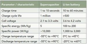
Leakage currents also vary by capacitance value, voltage rating, packaging style, and temperature. Leakage current drops to near zero at around -40°C and rises to ~650% of the 45°C value at ~85°C. Generally speaking, supercapacitors perform significantly better at temperature extremes than lithium-ion (L-ion) batteries over the mid- to long-haul.
Supercapacitor voltage ratings are commonly ~2.7 V per cell, but they can be stacked or packaged in series to reach higher voltages. The widespread availability of PMICs with cell balancing tends to dictate the economics of single cells configured by end users.
In the case of the energy harvesting RE01 MCU application, supercapacitor operating temperatures were about the same as for the RE01, and the cell voltages were adequate. The supercapacitor life cycle exceeded that of equivalent Li-ion batteries.
Start-up capacitor testing
To demonstrate the use of a tantalum start-up capacitor (C-SU = KYOCERA AVX P/N TPSC107K010R0200), consider two test cases: First, the C-SU used in conjunction with an ultraminiature supercapacitor stack. Second, a miniature supercapacitor stack but with a larger capacitance value.
Both test cases employ a 256KB RE01 evaluation board in a demo-mode loop. This board can also be powered with a combination of tantalum capacitors and supercapacitors. But the purpose of this test was to confirm that a tantalum capacitor can perform exceptionally well as a C-SU and to identify the operating life provided by the two different-sized (ultraminiature and miniature) supercapacitors.
The C-SU under test — 2.6-mm high occupying a total volume of 0.05 cm3 — takes up just 19.2 mm² of board space. Tantalum capacitors weigh less than competing technologies. This C-SU weighed approximately 170 mg. It also exhibits low and stable ESR. So its size, weight, stability, and reliability make it a good start-up capacitor for low- and ultra-low-power chipsets.
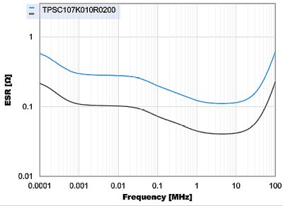
Power from the C-SU properly toggled, and the capacitor worked well in the normal demo mode of the 1500KB RE01 evaluation board. From an energy perspective, the demo execution mode consisted of C-SU charge, power source transition to C-bulk, C-SU secondary charge/maintenance, power transition to C-SU, supercapacitor recharge, and system shutdown cycles.
Two supercapacitor (C-Bulk) test cases provide representative data for end users who prefer to build their own custom radial stack and for those who prefer to deploy a

standard 5.4-V module package. The first test case consists of connecting two ultraminiature radial-can supercapacitors (P/N: SCCQ12B105PRB) in series to build a 0.5-F, 5.4-V rated stack. The second test case consists of a miniature radial module (P/N: SCMR18C105PRBA0) rated to provide 1 F at 5.4 V. (Note: Run-time results will likely vary from data reported here because end-user code and execution cycles won’t be the same as demo mode software.)
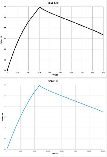
Test results revealed that larger C-Bulk devices store more energy and power the MCU longer than start-up capacitors.
Thanks to advanced tantalum start-up capacitors and bulk supercapacitors — energy harvesting generators can handle low-power IoT applications instead of batteries and mains. To that end, tantalum capacitors exhibit high levels of capacitance stability and low loss in small, lightweight packages and are available in consumer, automotive, commercial off-the-shelf, and high-reliability versions suited for the role of a start-up capacitor. The combination of tantalum start-up capacitors and high-energy-storage supercapacitors enables the use of energy-efficient MCUs in energy harvesting and scavenging set-and-forget IoT applications.
References
Demcko, Ron, et al., Powering IoT modules using solar panels, supercapacitors, and an automatic buck/boost controller IC, Kyocera AVX, 22 jan. 2021.
Zednicek, Thomas, High CV MLCC dc/ac bias aging capacitance loss explained, passive components blog, European Passive Components Institute (ECPI), 23 Sept. 2019.
Derose, E., Knopsnyder, B., & Rawal, B. (2018), Reliability of supercapacitors: Unique performance at 85°c & self-balancing (part 1), Kyocera AVX.
Derose, E., Knopsnyder, B., & Rawal, B. (2018), Reliability of supercapacitors: Long-term reliability test data (part 2), Kyocera AVX.



Leave a Reply