It pays to know techniques for mitigating leakage current and over- voltages in uses where several supercapacitors work in parallel.
Michele Kinman Advanced Linear Devices Inc.
In applications requiring rapid charge/discharge cycles or short-term energy storage, you’ll often find supercapacitors connected in series or parallel. However, there’s a potential problem when supercaps are wired together in banks: No two supercaps are identical, a fact that may lead to a slight voltage imbalance between them.
More specifically, these imbalances arise because the individual capacitors in capacitor assemblies each have minuscule variances in their make-up that contribute to slight differences in their electrical properties such as capacitance, internal resistance, and leakage current. In particular, supercapacitor leakage current depends on parameters such as aging, the material/construction of the supercapacitor, and the operating bias voltage. Leakage current is also a function of the charging voltage, the charging current, operating temperature range, and the rate-of-change of many of these parameters.

The usual way of accommodating these changing conditions is with a balancing circuit. Here, added balancing circuitry ensures weaker capacitors don’t drain stronger units during discharge and that individual capacitors don’t see overvoltages during charging. Large-cell supercapacitors, in particular, require over-voltage balancing because these cells can incur large energy flows.
The simplest supercapacitor balancing circuit consists of a resistor put in parallel with the capacitor terminals. Resistors with the same value in parallel with all cells allow cells with higher voltages to discharge through the external resistor at a higher rate than the cells with lower voltages, thus distributing the total capacitor bank voltage evenly across the capacitors.
The problem with this scheme is that the resistor constantly dissipates power as it conducts. When capacitance values of supercapacitors become larger, for values ranging from 100 F to 1,000 F, the capacitor mismatch problem becomes more pronounced and more difficult to correct, especially if capacitor balancing also requires ultra-low power consumption. The typical approach is to devise a balancing circuit containing a switch (usually a MOSFET) in series with a resistance. The switch keeps the balancing circuit off, and dissipating no power, unless cells are out of balance.
One difficulty with this approach is that the small MOSFET current meant for correcting leakage current imbalances may be too small if there is too much variation among the supercap cell tolerances. Designers avoid this problem by characterizing the supercaps they use and ganging together those having capacitive values that are close to each other.
Typical applications
Experts say 5G base station infrastructure could consume three times more power than its 4G LTE predecessor. One reason is that 5G needs three times as many base stations for the same coverage as LTE due to the higher frequencies used. In addition, typical 4G base stations now use four transmitter and four receiver (4T4R) elements, while 5G is expected to use 64T64R MIMO arrays.
Consequently, there is much interest in making 5G base stations super energy efficient. One point to note is that today, a 4G base station consumes a significant amount of energy even when there is no output power. The reason is that most 4G circuitry remains active to transmit mandatory idle mode signals — such as those for synchronization, reference, and system information –defined in the 4G standard.
But 5G NR base stations (i.e. those that are not backward-compatible with LTE) will be in a sleep state when there is no traffic to serve. NR entails far fewer always-on signaling transmissions than LTE (where required signal transmissions are typically less than 1 msec apart). Thus 5G NR base stations are expected to see both deeper and longer periods of sleep with little or no ongoing data transmissions, significantly enhancing overall network energy consumption.
5G NR base stations coming out of sleep mode will have spiking power demands that are well suited to power supplies incorporating supercapacitors. Here, use of supercaps can make it practical to employ a power supply that is smaller than would otherwise be necessary, further boosting energy efficiency. Ditto for the UPS used to back up 5G NR base stations.
Other examples of applications that need large supercapacitor banks and near-zero power waste include autonomous transport systems ranging from large off-road vehicles to small robotic rovers loading and unloading trucks, as well as automated guided vehicles that roam the factory floor. Supercapacitors, typically with values of 3,000 F at 2.7 V, are linked in series and parallel in these applications.
Large trucks and off-road vehicles today still generally have a propulsion system incorporating an internal combustion engine and an intelligent powertrain that needs a high-precision and energy-efficient power supply; it can be challenging to design their energy storage systems to handle high-transient-current conditions such as cold starts. (Electric locomotives have similar starter systems.) In this regard, supercapacitors will instantaneously supply pulse power to kick-start these large engines, even from a cold start.
This past Dec., General Motors won a 2019 R&D 100 Award for its capacitor-assisted battery (CAB) technology that it intends to use on future GM vehicles. This hybrid cell increases cold-cranking battery performance and allows the electrical power system to offset temperature impacts on lithium-ion battery supplies. Developed at GM’s China Battery Lab, the new hybrid cell is expected to impact low-voltage and hybrid electric vehicle systems, as well as non-automotive applications requiring high-power response. It has already been licensed to two global battery manufacturers for mass production.
In autonomous transport systems, supercapacitors must also be able to work over a high duty cycle and handle frequent deep discharges. Supercapacitors help power start/stop systems, as well as regenerative braking systems, work better.

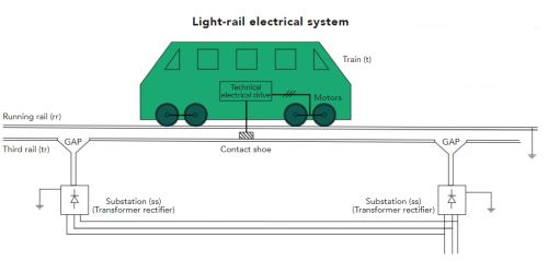
a single train which is traveling between two substations.
Railways are exceptionally energy efficient in terms of energy per passenger mile. (The American Bus Association puts energy use of light rail at about 1,800 btu/passenger mile. For comparison, ABA estimates the average car trip at about 3,800 btu/passenger mile.) Rail cars use regenerative braking to absorb energy and store it in both batteries and supercapacitors. Supercapacitors are perfect in this application. Besides sitting on the train itself, banks of supercaps can be installed at stationary points along the track.
Consider traction power substations, which provide power to the overhead catenary system or third rail. The substation converts utility power from 13.2 kVac to the 750 Vdc that the trains use and transmits it via the contact system. Energy generated by decelerating vehicles typically feeds into the traction electrification system incorporating supercapacitors. Supercaps usually sit in substations to power rail cars. The supercaps get energy both from the electrical utility and fed from rail cars themselves as their regenerative braking systems decelerate them.
Alternatively, some rail installations also use capacitor-equipped rail cars to absorb regen power. Placing supercapacitor units onboard rail cars reduces power substation loads and permits the light-rail system to expand without the expense of additional substations.
One reason supercapacitors make sense for light rail is that rail cars might go through 100,000 to 300,000 cycles of acceleration, running, and deceleration annually. Many battery technologies would wear out quickly with this sort of load profile, but it is no problem for supercaps. Additionally, supercapacitors are lighter than a comparable battery, advantageous when the supercap sits on a rail car.
Supercapacitor banks also have a place in low-inertia power grids. Here grid inertia refers to the kinetic energy in the electricity grid. This kinetic energy is that of the conventional generators at power plants which rotate at the same frequency as the electricity grid. Thus low-inertia systems are those with a significant amount of non-synchronous renewable energy sources such as solar and wind.
The problem with low-inertia grids is they may not be able to provide the inertia to support grid frequency and can be susceptible to issues of power quality and blackouts. When power demands spike, the frequency of the grid tends to drop. In grids having a great deal of traditional rotating generator capacity, the rotating mass functions as a shock absorber in the event of sudden heavy loads.
Solar panels, of course, have no rotating mass. And because wind turbines connect to the grid through a frequency converter, the wind turbine’s rotating mass doesn’t provide inertia when grid frequency drops.
Supercapacitors can play a role in grid stabilization by providing reactive power, power attributed to ac current and voltage that is out-of-phase with each other. Reactive power, measured in volt-amperes-reactive, helps regulate grid operation and is necessary for operating loads such as motors and transformers. Reactive power does not travel as far as real power. Long transmission lines operating at heavy loads can cause conductor heating and falling voltages because of the reactive power component associated with the distributed L-C of the power line.
In this regard, supercaps can be positioned close to power loads to serve as a fast source of reactive current. Lowering the reactive current demand allows the delivery system to carry more real current and helps the utility maintain its service voltage within required limits.
Supercapacitors can as well play a role in renewable energy applications. Applications powered by solar panels typically incorporate deep-cycle batteries sized for the application’s total watt-hours per day of use. Supercapacitors used as an addition to the battery capacity brings several benefits. Perhaps most obvious is that supercaps can handle short-term spike loads to permit use of a smaller and less costly battery bank. The fact that supercapacitors use physical rather than electrochemical charge storage and so have a practically unlimited cycle life comes in handy as well. And because supercap equivalent series resistance (ESR) doesn’t vary appreciably with temperature, supercaps can sit outdoors near the solar array.
In the same vein, supercaps can serve as a backup source of dc power for data centers. The vast majority of power glitches (87%) last less than a second. A supercop UPS system can sit in a smaller footprint and provide a higher power density than a battery backed-up UPS. UPS electronics can typically work up to 35-40°C without derating or a degradation in performance. But a UPS with sealed lead-acid (SLA) batteries has an optimum range of 20-25°C – the recommended temperature range for an SLA battery to reach its design life.
Finally, a supercap UPS recharges almost instantaneously compared to the time necessary for recharging a traditional battery set through the UPS rectifier or external battery charger.
These are only a small sampling of the applications where supercapacitors contribute to a reliable system design with a long lifespan.
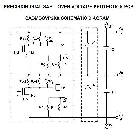
One development that helps promote reliable supercap applications comes from Advanced Linear Devices which has a precision dual-channel PCB called the SABMBOVP2XX family that not only automatically balances supercapacitors but has an additional over-voltage protection (OVP) feature. One more added benefit of this series is that it performs all these tasks at ultra-low power with leakage current regulation. It can be said that this solution has zero power burn.


Leave a Reply