
Size constraints and a need for high efficiency are forcing designers to use more sophisticated current sensing techniques in modern electronics.
Teoman Ustun, ACEINNA
The historical mindset of power design being an afterthought in the overall system architecture is changing. Before the focus of electronic design shifted to power efficiency, it was a common practice to simply add a power circuit to a system design once it was finished. This practice would simply not work today as power handling must be intrinsic to circuit control and monitoring.
The issues created by faulty power handling may cause intermittent performance problems which are extremely difficult to reproduce, especially during development. This problem is exacerbated once a system is deployed in the field; initial performance issues can cause cascading problems throughout the system that require expensive troubleshooting.
In recent years wide-bandgap materials have become available with significantly higher levels of performance than silicon in the areas of electron mobility, temperature, and switching speed. These materials are gallium nitride (GaN), a piezoelectric semiconductor that is well-suited to low-power and high-speed switching apps, and silicon carbide, whose remnants are sold to the jewelry industry as moissanite “artificial diamond” and can handle power and thermal levels far above those practical for silicon-based circuits. Silicon is still the go-to material for microcontrollers and other logic devices but its days as a power semiconductor are numbered.
The ability to handle higher levels of power at a higher efficiency is already a game-changer, but the ability to switch at high speeds also enables the entire circuit to shrink, as you can use smaller passives such as capacitors and inductors, reducing board space used as well as weight. This extends beyond simple space savings, as the higher switching speed of GaN, for example, enables high-frequency systems like LIDAR to be driven in an optimum manner.
Mastering control
Another major aspect of modern power electronics is the ability to control the circuit down to the point of load, a capability that emerged in the last decade or so. This movement arose from the initial adoption of distributed power architectures, where a bus converter on the board sent power to individual point-of-load (PoL) converters sitting near devices to be driven. And this divided architecture could be controlled digitally.
This digital control was first standardized under the PMBus protocol, although there are other proprietary control methodologies available. The key is that each power device on the board can be addressed, polled, and controlled remotely. This setup enables a granular, optimized, and efficient way to manage power on the board. And the polling ability provides a way to obtain data on important aspects like a thermal map of the entire circuit.
Digital power management is at the core of the Internet of Things; control of any electronic system also entails control of power. In this context, current sensors are becoming increasingly important in power converter applications. For example, dc/dc switching applications achieve high efficiency via fast switching currents. Numerous control algorithms also depend on real-time current measurements.
The increased performance of wide-bandgap semiconductors has pushed other components on the board to boost performance to match, and the latest topologies demand the latest in protection and control methodologies. For example, smart power techniques require the use of monitoring devices such as advanced current sensors. These sensors measure current bidirectionally to both protect the circuit and batteries against abuse and to optimize performance.
The high energy densities and accelerated battery charge/discharge times that characterize modern electronics have brought more stringent requirements for current sensing. In the case of high energy-density batteries such as lithium-iron-phosphate (LFP) or lithium-titanate-oxide (LTO, sometimes just called lithium-titanate) require coulomb counting to determine battery state-of-charge (SoC), state-of-health (SoH), and state-of-function (SoF).
Increasingly, traditional fuses are inadequate for advanced over-and undercurrent protection of power systems employing wide-bandgap semiconductors. Use of a fuse for circuit protection also doesn’t provide any feedback on the real-time performance of the power electronics. To protect from overcurrent conditions and improve safety, IC devices such as those from ACEINNA respond quickly and handle a large current measurement range. The isolated devices can operate in both the high and low sides of the power circuit, and their integrated construction simplifies the protection scheme compared to a shunt-plus-amplifier approach. Using ACEINNA current sensors in high side, ground faults of the phase current (possibly due to wrong wiring, aging etc.) can also be detected.
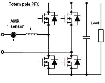
The advantages of isolated current sensors such as those from ACEINNA become evident in the specific example of a totem-pole power factor correction (PFC) circuit. One such design uses a SiC-MOSFET C3M0065090K from Wolfspeed as its high-frequency switches and a IXFH80N65X2 from IXYS as the low-frequency switches. The SiC-MOSFET provides the breakdown voltage needed and can dramatically reduce the reverse-recovery loss so the totem pole PFC can work in CCM (continuous conduction mode) to support higher power.
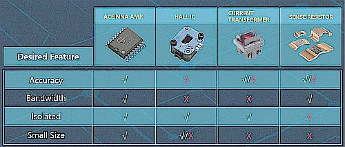
For traditional PFC designs, typically a shunt resistor is connected to the input of an op-amp is placed in the ground line to sense current. But in totem pole PFC designs, there is no ground line, so there’s no way to add a current-sensing shunt resistor as in a traditional PFC. That leaves designers with three other ways to sense current: current transformers (CTs), a shunt resistor with an op-amp and an isolator, and magnetic current sensor modules or ICs.
A CT can sample the current through the main inductor. However, a CT can only work in ac. To sense switching current, it would take three CTs to sample and integrate the inductor currents in the positive and negative cycle through the MOSFET and rectifier. And unfortunately, CTs also suffer from nonlinearities and hysteresis over temperature.
Another way to measure current is to insert a current shunt in series with main inductor. This approach requires an op-amp, an isolator, and a separate isolated power supply with multiple passive components around the isolator and op-amp. The circuit design is complex and adds to the space needed to house the PFC. Additionally, applications using higher currents must use accurate low-value resistors to minimize power dissipation, and these resistors can be costly. Further, output response time is slow because there is an opto-isolator and op-amp in the signal path. The combined output step response time can easily be over 1 µsec.
An isolated magnetic current sensor module or an IC containing Hall Effect or AMR (Anisotropic Magneto-Resistive) magnetic field sensors is another widely used method of current sensing. These magnetic current sensors provide the required isolation and do not need separate isolated power supplies. However, there are two major challenges with regard to magnetic current sensors.
First, traditional Hall Effect sensor modules or ICs typically have a bandwidth of about 120 kHz at best. That’s fine for 60-Hz PFC current, but the slow output response (related to bandwidth) can’t support the time frame needed for peak and over-current protection for fast switching currents.
Second, Hall effect magnetic current sensor modules are relatively large because they contain a ferrite core. The size of current sensor modules adds to the space needed and thus reduces the power density of the PFC. Additionally, current sensor modules that have sufficient bandwidth and accuracy for this Totem pole design are relatively costly.
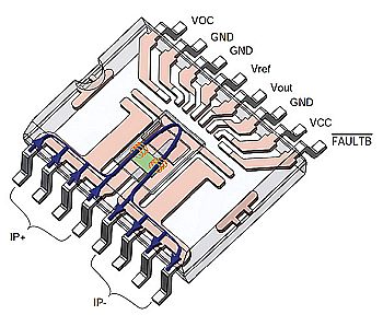
Now consider a Totem pole design employing a high-accuracy, 4.8-kV isolated AMR current sensor IC (MCA1101-50-5) from ACEINNA to sample the inductor current. This ±50-A sensor IC has a typical accuracy of 0.6%, 1.5 MHz bandwidth, and output response time of 300 nsec. It provides reinforced isolation and meets UL60950 with no additional isolated power supply. It includes an Over Current Detection (OCD) threshold that can be set on the IC and a fault-flag pinout designed to interface with an MCU to trigger an interrupt in the event of an over current.
The MCA1101 provides many advantages for a Totem Pole PFC application. These include high accuracy over temperature, high bandwidth, fast response, use of a single power supply, reinforced isolation, a programmable OCD voltage and a fault pin to provide current information to an MCU.


Leave a Reply