Quantifying the performance of switch-mode power converters is an increasingly important aspect of system design. Systems are often required to meet standards for efficiency, standby power, power factor, harmonic distortion, and more. Switch-mode power converters have large capacitors connected to the ac input, resulting in complex input waveforms. Their performance cannot be analyzed correctly based on simplified assumptions of sine wave voltage and current inputs. This FAQ will review the basics of ac power measurements that will provide the foundation for discussing how to verify certain aspects of power converter performance in the next FAQ.
Root mean square ac measurements
The root mean square (RMS) measurement is the most commonly used value to measure ac currents and voltages. The RMS value is equivalent to the amount of dc power that would result in the same power dissipation in a purely resistive load. Calculation of the RMS value using the “amplitude” format can be useful. The amplitude, “A” in the figure below, can represent voltage, current, or other parameters.
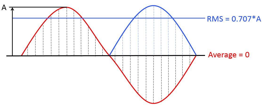
An ac voltage waveform oscillates above and below zero with an average value of zero. That is not a good measure of the effective voltage. The RMS value is used to derive the equivalent steady-state value. Using the amplitude (or peak value) format, the RMS value is calculated by squaring the peak amplitude, “A”, of the wave, dividing it by two to find the mean value, and then taking the square root of the resulting value. For a simple sine wave, the RMS value can be represented as 0.707*A.
For more complex waveforms, the RMS value is defined as the square root of the arithmetic mean of the squares of the values (consider the equivalent of the vertical “slices” in the image above), or the square of the function that defines the continuous waveform. RMS values are especially useful when making power calculations, and listed voltages for power outlets are usually listed in RMS values, not peak values. The peak value is equal to the RMS value multiplied by the √2. In the case of 120Vac, for example, the peak voltage is about 170Vac. With European mains voltages, the peak value is about 325, and the peak-to-peak voltage is about 650V
Crest factor
The ratio between the RMS value and the peak value is called the waveform’s crest factor and is defined as: crest factor = peak value/RMS value. For a sine wave: peak value = RMS x √2; and the crest factor is √2, or about 1.41.
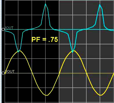
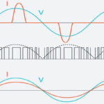
Most electronic power converters such as ac-dc power supplies, motor drives, and lighting power supplies have large capacitors on the input that result in non-sinusoidal currents with crest factors much larger than 1.41. A typical switch-mode power converter has a pulsing AC input waveform. The crest factor is often above 3 for these power converters. That means that the ac power distribution network must support the high crest factor, not just the average power level. As discussed below, this is one of the driving considerations behind requirements for power factor correction where the crest factor is reduced to a value closer to 1.41 as found in a typical sine wave.
Power: real, reactive, apparent, and the power triangle
If the load is purely resistive, the current and voltage waveforms are sinusoidal, and the two quantities reverse their polarities at the same instant. Power flows only in one direction and is called true power or real power.
In the case of a purely reactive load, the voltage and current are 90 degrees out of phase. And reactive power “flows.” The power (product of the voltage and current) is positive for two quarters of each cycle and negative for two quarters. As much energy is flowing into the load, there is no net energy transfer out of the load. But current is flowing in both directions, and the wires must be sized to carry that current, even if the load itself consumes zero energy.
Real loads consist of a combination of resistance, capacitance, and inductance. Both active and reactive powers are present, resulting in apparent power, which is the product of the RMS values of voltage and current. Apparent power must be considered when designing power distribution networks. Wiring and other current-carrying components must carry the total current, not just the current resulting in useful work.
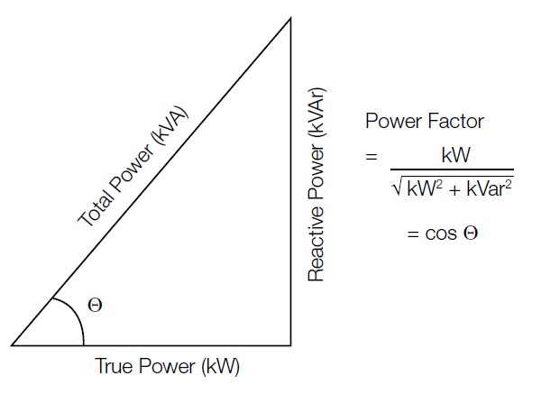
Real, or “true,” power is measured in Watts. Apparent, or “total,” power is measured in volt-amps (VA) and is the product of the RMS voltage and RMS current. Finally, reactive power is expressed in VAr, which stands for volt-amp-reactive. Reactive power is also referred to as “wattless power” since it transfers no net energy to the load. As illustrated below, the power factor measures the ratio between total power and true power (or the ratio between apparent and real power). A load with a low power factor draws more current than a load with a high power factor for the same amount of useful power transferred. As the reactive power decreases (the load becomes more purely resistive), the total power and true power become equalized, and the power factor approaches unity.
In ac-dc power supplies, active power factor correction (PFC) controls the current flowing into the power supply to improve the power factor. A boost converter is inserted between the bridge rectifier and the main input capacitors in single-phase power supplies. The boost converter (PFC stage) is controlled to maintain a constant voltage at its output while drawing a current in phase with and at the same frequency as the ac line input.
Power factor: positive and negative, displacement and distortion
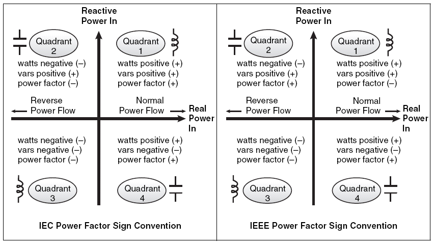
The sign (positive or negative) of the PF depends on the standard being used and is different for the IEC and the IEEE. Using the IEC standard, the direction of real power flow determines the sign of the PF. the PF is positive for “normal” (positive) real power flow when the load is consuming energy. The PF is negative for “reverse” (negative) real power flow when the load generates energy.
According to the IEEE, the PF sign only depends on the nature of the load, not the direction of real power flow. For a capacitive load, the PF is positive, and for an inductive load, the PF is negative. Note that whether using the IEC or IEEE sign convention, the PF’s absolute value does not change; only the sign changes.
“Displacement power factor” can occur in circuits with sinusoidal currents and voltages. The power factor results from the difference (displacement) in phase between the current and voltage. “Distortion power factor” is the distortion element associated with various harmonic currents and voltages associated with nonlinear loads. Nonlinear loads change the shape of the current waveform from a sine wave to a different waveform, such as a pulsing wave. As a result, nonlinear loads tend to create harmonic currents, contributing to the distortion power factor. For nonlinear loads, knowing the crest factor is useful when quantifying the level of distortion.
Harmonic distortion
Harmonics in an ac electric power system are voltages or currents at a multiple of the fundamental system frequency. Harmonics are caused by non-linear loads such as telecom rectifiers, variable speed drives, lighting ballasts, and ac/dc power supplies. Semiconductor devices such as diodes, transistors, MOSFETs, and IGBTs are also examples of nonlinear loads. Harmonics in the power grid can cause power quality problems, resulting in increased heating in the conductors and other components in the grid. Under normal operation, electric motors do not contribute significantly to harmonics. But both motors and transformers can create harmonics if they are over-fluxed or saturated.
Total harmonic distortion (THD) is a measure of the overall distortion present. It is defined as the ratio of the sum of the powers of all harmonic components to the power of the fundamental frequency. Distortion factor is a closely-related concept and is sometimes used as a synonym for THD. Regulations limiting the acceptable levels of THD are widespread and are often based on EN61000-3.
The next FAQ will consider how the various ac power measurements discussed above can verify ac/dc power supply performance. The third and final FAQ will review important considerations when validating power integrity in embedded system power distribution networks.
References
Fundamentals of ac power measurements, Tektronix
Power Factor, Wikipedia
What is the difference between IEEE and IEC PF standards, Schneider Electric




Short but nice and useful explanation, good work.