
Induction heating is widely used in industry and even consumer appliances as a contact-free heating technique with many distinct advantages.
The understanding of induction heating begins with basic electromagnetic principles and that very ancient electrical component still in very wide use: the transformer. However, an induction-heating transformer does not resemble a standard AC-line power transformer, signal transformer, or RF transformer, even it has the same schematic and underlying principle (Figure 1).
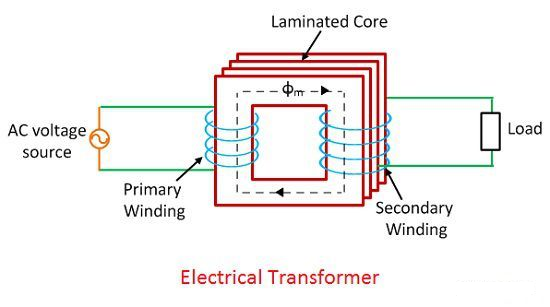
Induction-based heating begins with a coil of a conductive material such as copper. The induction heating arrangement is a form of “open” air-core transformer design without the conventional core used to contain the magnetic flux and maximize efficiency. As current flows through the coil, it produces a magnetic field in and around the coil.
This primary-side current must be a non-steady, non-DC, alternating current (AC) for the transformer induction to work, again following Faraday’s discovery (we’ll look at the frequency of this AC later). The ability of the of the magnetic field to do work depends on the coil design as well as the amount of current flowing through the coil.
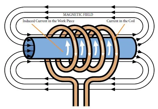
The driven inductor serves as the transformer primary side while the part to be heated – often called the workpiece – becomes the secondary side (even though it is a low-resistance or even short circuit. When a magnetic (ferrous) or non-ferrous metal part is placed within the inductor and enters the AC magnetic field, circulating currents called eddy currents are induced within the part (Figure 2).
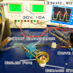
The current transmitted through the secondary side is proportional to the inverse of the square of the distance between them. Since there is no magnetic core to direct and constrain the flux, the secondary side or workpiece is usually surrounded by the primary coil, to maximize the transfer of magnetic energy transfer (Figure 3). (This is not the situation in consumer-appliance designs, discussed in Part 4).

As the eddy currents flow through a medium, there will be some resistance to the movement of the electrons. The eddy currents flow against the electrical resistivity of the metal, and they generate localized heat without any direct contact between the part and the inductor.
Thus, induction heating is a form of I2R heating, except that the “connection” between power source and heating element is not a direct wire connection with electron flow. Instead, it is an alternating magnetic field which induces electrons to move – that’s current flow – and this movement of electrons encounters resistance in the form of the resistivity of the metal, which then causes heating.
This heating occurs with both magnetic and non-magnetic electrically conductive parts. From a physics standpoint, this is often referred to as the “Joule effect”, referring to Joule’s first law which defines the relationship between heat produced by electrical current as it is passed through a conductor.
There is another heating mechanism at work in some cases. Additional heat is produced within magnetic parts through hysteresis and hysteric heating, – internal friction that is created when magnetic materials pass through the varying magnetic fields which modify the component’s magnetic polarity. This resistance also produces internal friction which in turn produces heat.
However, this secondary effect of hysteretic heating only occurs in a component up to the Curie temperature, the temperature at which the material’s magnetic permeability decreases to unity (typically, 500-600°C/1000-1150°F). In contrast, the heating due to eddy current continues.
One of the important attributes of the standard electrical transformer is that it provides galvanic (ohmic) electrical isolation between primary and secondary sides using a changing magnetic field to transfer energy across a barrier. This is also the case with induction heating. The material to be heated can be located in a setting isolated from the power supply’s primary side; it can be grounded, submerged in a liquid, covered by isolated substances, in gaseous atmospheres, or even in a vacuum.
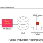
The next part of this article looks at the overall induction-heating system and some important overall characteristics.
Related EE World Content
- Using Faraday’s Law of Induction
- Reverse-conducting IGBT targets induction heating apps
- What advanced sensing techniques are used to find lost treasures? Part 2: Electromagnetic induction
- IGBTs Reduce Cost in Induction Cooking Designs
- Basics of induction
- AC challenges with inductors
Additional References
Professional and Industrial References
- Wikipedia, “Induction heating”
- AZO Materials, “What is Induction Heating and How do Induction Coils Work?”
- GH Induction Atmospheres, “What Is Induction Heating?”
- Inductoheat, “What is Induction Heating?”
- RDO Induction L.L.C, “Fundamentals of Induction Heating”
- UltraFlex Power Technologies, “How Induction Heating Works”
- Wikipedia, “Royer Oscillator”
Consumer Use References
- Wikipedia, “Induction Cooking” (has efficiency numbers)
- Consumer Reports, “Pros and Cons of Induction Cooktops and Ranges”
- Martha Stewart, “The Pros and Cons of Induction Cooking”
- Don’s Appliances, “Induction Cooking: What is it and How Does it Work?”
- CDA, “How does induction cooking work?”
Do-It-Yourself References
- Homemade Circuits, “2 Simple Induction Heater Circuits – Hot Plate Cookers”
- Homemade Circuits, “How to Design an Induction Heater Circuit”
- Innovation Discoveries, “How to build and induction heater and how does it work?”
- RM Cybernetics, “How Does Induction Heating Work?”
- Autodesk/Instructables, “DIY Powerful Induction Heater”

Leave a Reply