How a motor ramps its angular position or rotational velocity from a starting point to the intended target value is a complicated topic which modern motor controllers address in many ways.
Controlling the motion of a motor is a major design challenge since how a well a possible motor choice can ramp its speed and position is a prime factor in determining how well it suits the application. For all except the simplest low-end situations, such as a cheap toy, motor control is a complicated topic with many solutions, each with different “optimum” performance metrics. There is no single “best” motor and motion-control in many engineering situations. Still, instead, there is a complicated set of possibilities, with each offering a different balance among many factors and tradeoffs.
There are multiple reasons for this complexity. The motor world consists of almost countless groups, variants, and sub-variants within the two basic AC- and DC-supply groupings. There is no “perfect” or even very good moto- family tree or genealogy, as each one is created with the legitimate perspectives and biases of their source or author, as demonstrated by Figures 1, 2, and 3. One thing is certain: each motor type or group has different attributes, offers different performance characteristics, and will require different controller specifics.
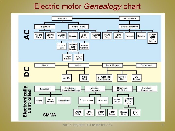
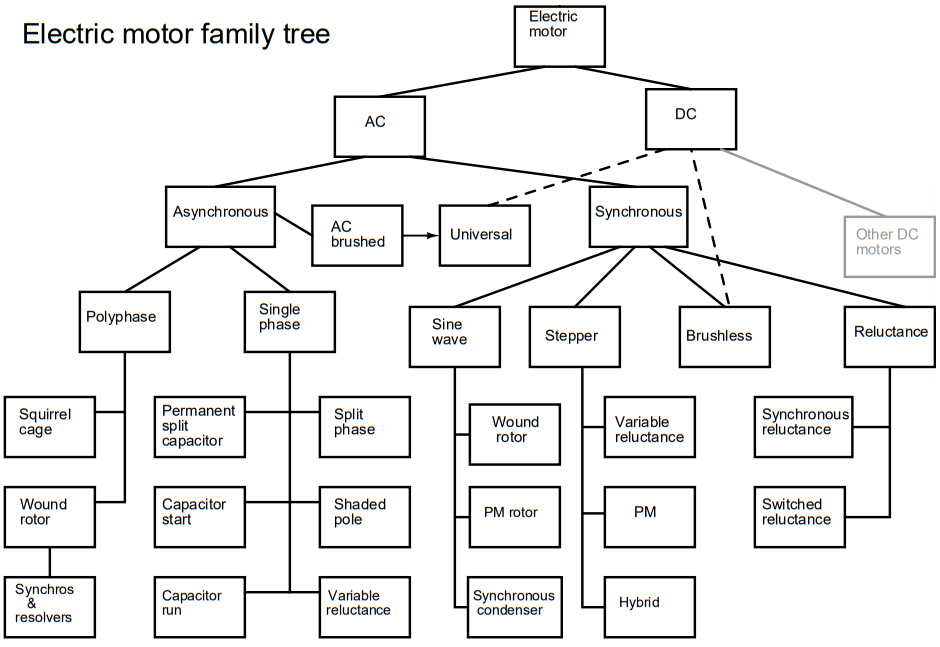
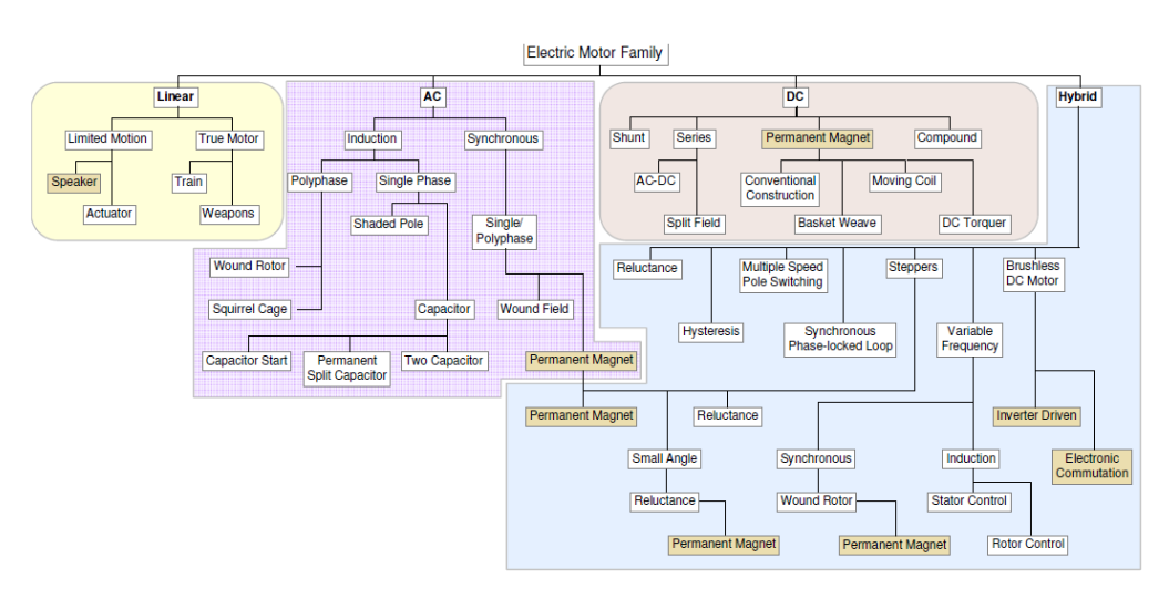
For many engineers, the motors of greatest interest are brushed DC motors, brushless DC (BLDC) motors (also called electronically commutated or EC motors, stepper motors, and AC motors. Note that while it may seem that there is a firm line between AC and DC motors, it’s also a matter of perspective as it is possible to make the case that a BLDC/EC motor is really an electronically commutated AC motor.
Parameters and priorities
The other reason for motor and motion-control complexity is that many factors characterize what each type is potentially “best” at doing. These include:
- absolute rotational positioning and accuracy;
- rotational speed (rpm) and accuracy;
- acceleration;
- deliverable torque;
- amount of overshoot on position and speed;
- required time and ramp rate to reach desired position or speed;
- acceleration constraints, and minimum/ maximum rate of change in acceleration (formally designated as “jerk”);
- up-front costs as well as ongoing operating and energy costs.
For example, some applications emphasize fast transfer time between point A and point B on the position or velocity target. These include gantries, high-speed stitching, electronic pick & place machines, plotters, robotic arms, antenna/tracking systems control, and 3-D printing systems. Others are more focused on smooth motion with minimal jerk, even at the expense of reduced speed, such as medical or chemical analysis automation, elevators, medical diagnostic scanners, semiconductor processing, equipment, and scientific instrumentation. Having design priorities (here, speed versus smooth motion) does not mean that the other parameters are of no interest; instead, it’s just a relative weighting among them which matters.
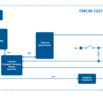
The role of the motor controller is to modulate and deliver the voltage or current to the motor as needed to implement the desired performance with respect to the above parameters, based on high-level instructions from the system processor (Figure 4).
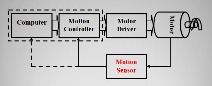
This modulation is accomplished by increasing or decreasing the voltage or current drive to the motor or by pulse-width modulation (PWM) of the drive voltage/current. The choice is partially a function of the motor type in addition to performance priorities; for example, PWM is generally more energy-efficient than analog modulation of the voltage or current but may induce chatter or “jerky” motion.
It’s also important to realize that the motor alone is not the ultimate load of the motor controller but that whatever the motor itself is driving is. This means that any motor-drive and -control analysis must also consider the specifics of that load: its mass, nature (stiff or flexible), changes in the load (bottles being filled), and more. There are major issues of system resonance and inertia which must be evaluated as well.
Open-loop or closed-loop
Another major consideration in motor and motion control is whether there will be feedback from the motor or its load to support closed-loop control. The feedback sensor is usually a rotary encoder, optical encoder, or Hall-effect device. Each offers tradeoffs in cost, resolution, ruggedness, and installation difficulty. Whether to use feedback or not is determined by accuracy and performance requirements, and priorities.
If feedback is used in a closed-loop arrangement, the motion controller must embed a closed-loop algorithm, usually a PID (proportional-integral-derivative) scheme or some variation of that widely used approach. Keep in in that regardless of which feedback sensor is used, they report on rotor position, which can be absolute or relative, depending on the sensor type and set-up. If the motor control is focused on velocity or acceleration rather than position, then the position signal and data must be differentiated with respect to time once (for velocity) or twice (for acceleration).
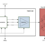
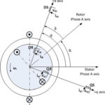
In recent years there has been a friend to sensor-less feedback based instead on real-time measurement of the motor current or back electromotive force (EMF). Doing so requires basic current or voltage sensing and is much simpler, less expensive, more reliable, and easier to accomplish physically than a separate feedback sensor. Such sensorless feedback, often using field-oriented control (FOC) algorithms (also called vector control), is now a viable option in many cases due to increases in digital signal processing performance, enabling the execution of sophisticated algorithms which can provide impressive control results.
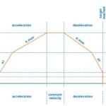
The remainder of this article will look at issues related to the motor’s motion-control profile, often called “ramping” or “trajectory.” It will not look at the various motor technologies as that is another complicated topic, although obviously related. In general, motors are a complex subject with many subtleties, guidelines, exceptions, and electromechanical issues. Part 2 of this article looks at some common ramping options.
EE World Related Content
Basics of AC, DC, and EC electric motors, Part 1— AC and DC
Basics of AC, DC, and EC electric motors (Part 2) — EC and stepper
What is Proportional (PID) Control and why is it used? (Part 1)
Motor field-oriented control, Part 1: Principles
Motor field-oriented control, Part 2: Implementation
Motion control ICs handle advanced velocity control of servomotors
Motor controller includes three-phase gate driver and voltage regulator
References
Performance Motion Devices, “Servo Motor Tuning – Rocket Science or Walk In the Park?
Performance Motion Devices, “New Control Technique Combines Servo Performance With Step Motor Cost
Performance Motion Devices, “Mathematics of Motion Control Profiles”
Performance Motion Devices, “S-Curve Motion Profiles – Vital For Optimizing Machine Performance”
Performance Motion Devices, “Juno Family of Velocity & Torque Control ICs”
Trinamic Motion Control, “Motion Control Technology”
Trinamic Motion Control, “TMCM-1321 servo controller/driver module”
Texas Instruments, Application Note SPRABQ7A, “Sensorless Trapezoidal Control of BLDC Motors (Rev. A)


Leave a Reply