Most consumer devices that transfer power over wireless links follow the Qi standard. The construction of these power transfer systems is simpler thanks to the availability of new reference designs.
Contributed by IDT Inc.
Examine the wireless charging setup used in the passenger compartment of most vehicles and you are likely to find a system that follows the Qi standard. Promoted by the Wireless Power Consortium, Qi applies to power transfer over distances of up to 40 mm (1.6 in). Charging takes place via magnetic induction between a charging pad and a compatible wireless receiver.
Qi divides charging into low and medium-power categories. Low-power covers up to 5-W chargers as are typical of smartphones, Bluetooth earpieces, and so forth. Charging takes place via a signal in the 110 to 205 kHz range. Medium-power chargers deliver up to 120 W via signals ranging between 80 and 800 kHz.
A limited data transmission takes place between the charger and the mobile device being charged. Transmitted data provides information about the state of charge and similar parameters so the charger can shut down when the battery is charged.
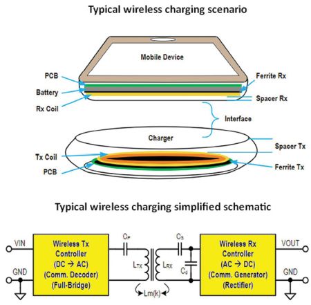
The charger first begins charging when it detects a change in capacitance or resonance in its transmitter coil. When the charger detects an object, it sends an 8-bit data string on the charging carrier. The mobile device then must respond with information about the signal strength it detects. The charger in turn sends multiple pings back indicating the optimum positioning for the mobile device. Charging commences when the mobile device has been validated and positioned correctly. During the charge process, the mobile device sends data packets (at about 2 kbps) that adjust the power level and finally end charging.
Qi chargers also can sense the presence of foreign objects in the charging field. When this happens, the charger cuts out.
Transmitter design
All wireless transmitters have four common building blocks: transmitter coils and resonance capacitors, a full or half-bridge inverter, a modulator/demodulator handling communication packets, and circuits that sense power transfer and protect against conditions arising from factors such as foreign objects in the resonance field.
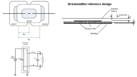
Several factors drive decisions about the design of specific Qi chargers. The desired maximum output power determines charger circuit working voltages. A 5-W output can employ circuits on a 5-V supply; 10-W outputs demand 9-V supplies; 15-W outputs generally use 12-V power rails. The Qi specification spells out that transmitter and resonance capacitance.
The Wireless Power Consortium publishes transmitter reference designs that make recommendations for various transmitter qualities. For example, the WPC library of coil types defines coil mechanical details that include the dimensions, thickness, and the make-up of the coil layers; the ferrite shielding material and its thickness; and electrical details such as the circuit configuration, inductance, capacitance, input voltage range, and range of operating frequencies.
The reference design employs Litz wire – multistrand wire designed to reduce skin and proximity losses for frequencies up to about 1 MHz – and specifies the number of turns and inductance necessary for gain and coupling. Also specified are resonance capacitors that are a COG ceramic type (for high dielectric stability) and carry a 50-V rating for 5-W chargers, 100-V for those handling 15 W. The design as well dictates that FETs used for driving the charge coils have a low, guaranteed RDSon at a VGS = 4.5 V, as well as a low Ciss (total input capacitance) to minimize switching losses and time delays and a current rating above 8 A.
The reference design specifies several ancillary components for the transmitter bridge. They include ceramic decoupling capacitors placed near the switching FETs. These are designed to keep switching energy out of the rectifier stage. And a low-pass filter sits between the FET coil drivers and the resonant tank, used to meet CISPR25 EMI standards.
The reference design controls transmitter power by varying the frequency, duty cycle, or bridge voltage. Duty cycle variance takes place once the resonant frequency is fixed.
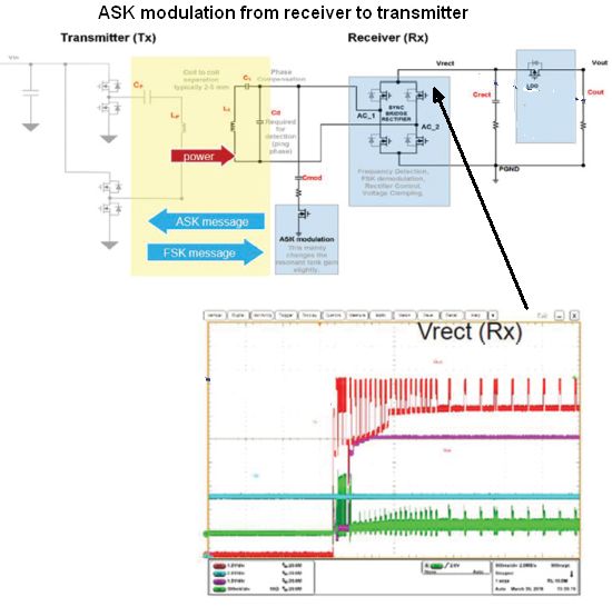
Communication between the transmitter and receiver takes place via ASK (amplitude shifted keying) and FSK (frequency shifted keying) with ASK used for sending data from the receiver to the transmitter, FSK for transmitter data going to the receiver. ASK communication is inherently slow. It is used to establish the power-transfer contract and may serve as a means of authorizing specific receivers to get charged. The receiver implements ASK modulation by switching a transistor on and off which changes the gain of its resonant tank slightly. The transmitter can detect this change to decode the ASK messages.
The capacitors used for generating the ASK modulation are generally 22-nF or 47-nF MLCC devices. One potential difficulty is that these MLCC caps can generate audible noise during communications because of the ac voltage across them. Substitution of a tantalum capacitor for some of the MLCC capacitance may help eliminate the noise. However, a point to note is that it’s generally best to apply a voltage derating to tantalum caps to avoid high failure rates.
The transmitter controller IC reads the ASK signal and may apply filtering to minimize the chance of data errors. That’s because the coupling process, any nearby permanent magnets, or transient loads can corrupt the ASK signal. The WPC spec. defines the ASK bit encoding scheme with each data packet including a preamble, header, message, and checksum. Each byte includes a start bit, eight-bit data, parity, and a stop bit.
To implement FSK, the transmitter shifts its frequency over a limited range. Its typical use is to send acknowledgements to the receiver though it may also send proprietary data packets. The modulation depth and polarity are established in the negotiation phase of the connection. The receiver IC demodulates the FSK data.
Qi systems use a control error packet (CEP) as a feedback mechanism to control transmitter power. The fastest CEP rate is about 50 msec/packet, and each CEP packet spans about 20 msec. The receiver calculates a value for the CEP by comparing actual battery voltage with a target. A positive CEP tells the transmitter to send more power by boosting the duty cycle or reducing the operating frequency. A negative CEP packet causes the opposite effect. If the transmitter doesn’t respond to the CEP, the receiver must shut down and send an End of Power Transfer signal.
There are several protection mechanisms for the charging process. Temperature detection circuits employ thermistor at the power transfer interface and limit the generation of heat. Over-voltage and over-current protection avoid short circuits and over-loads, low voltage (currents too high) and high voltage (too much energy transferred) conditions.

Facilities for foreign object detection (FOD) involve a continual calculation of power lost between the transmitter and receiver. The receiver periodically sends a received power packet (RPP) back to the transmitter. The RPP value is computed by first calculating the received power (rectified V×I), then multiplying by a gain and adding an offset. The gain and offset values are programmed in the receiver IC and depend on loading and the receiver modes. A difference in the power received vs. power transmitted triggers a shut down.
Wireless chargers of different power levels use different power-difference thresholds to shut down. For Qi BPP designs the power difference threshold is 350 mW. For the higher-power EPP designs there is a 350-mW threshold for 5 W, 500 mW for 10 W, and 750 mW for 15 W.

A further point to note is that it takes accurate sensing to distinguish between differing power levels caused by offset of misaligned receiving devices and those caused by foreign objects. That is one reason why EPP designs also do FOD based on a change in quality factor, Q. The operating principle is that a foreign object reduces the transmitting coil inductance and the series impedance, reducing the Q of the resonant circuit.
FOD based on a change in Q closely resembles that based on a change in received power. The receiver sends a reference Q to the transmitter, which then sets an appropriate threshold. Power transfer terminates if the measured Q is below the threshold. To realize this behavior, the procedure is to first sweep the frequency through resonance while recording the peak voltage and the two frequencies (one on either side of resonance) at which voltage is below the peak by 1/√2. Then Q is the resonant frequency divided by the difference between the upper and lower frequencies. A rise in the impedance facing the transmitting coil indicates the presence of a foreign object.
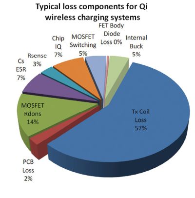
Finally, it is worth mentioning the energy efficiency involved in Qi wireless power transfer. An example comes from the IDT P9261 reference design, a 15-W wireless charging transmitter aimed at vehicle passenger compartments. This circuit provides an energy efficiency exceeding 70% when output power exceeds 8 W and more than 60% efficiency for outputs between 8 and 5 W. Examining the sources of transmitter loss reveals that coil losses make up 57% of the total losses, and MOSFET Rdson accounts for another 14%. Single-digit losses come from factors such as MOSFET switching, capacitor series resistance, PCB loss, and the current-sense resistor.
References:
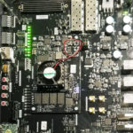
IDT Inc. P9261-3C-CRB automotive 15-W wireless charging transmitter reference board,



Thank you for sharing some extra info how a Qi Charger works.
It’s a lot more complicated than a DC-Alternating Current transformer with an oscillator and a coil, coupled to a receiving coil with some voltage smoothing.
Not an easy project to power a smartphone reliably.