
AC/DC and DC/DC power supplies usually are relatively rugged in regular operation. Nonetheless, some protection features are built into most of these units to ensure that they do not “self-destruct” or damage associated circuitry – primarily their loads – in the event of a failure or out-of-spec operational mode.
(note: in strict terms, a power supply is either an AC/DC or DC/DC unit, but the latter are also called converters or regulators as well. However, the usage associated with these terms is often sloppy, especially in casual conversation.)
Isn’t a fuse needed to protect the supply and the load?
Yes and no. A fuse protects the supply if the load-path short circuits or begins to draw too much current. A fuse may not be needed, as many supplies “self-limit” because they can only supply up to a certain amount of current. A fuse that opens will need to be replaced manually, which is a problem in many applications (but a virtue in others). Plus, a fuse cannot protect against other types of failure or misoperation, other than too much current on the output.
What is Undervoltage Lockout (UVLO)?
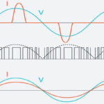
UVLO ensures that a DC/DC converter does not attempt to operate when the input voltage it sees is too low (Figure 1). This is done for two reasons: first, circuitry within the converter may malfunction or act in an indeterminate way if the input DC voltage is too low, and some higher-power components may actually be damaged; second, it prevents the converter from drawing on primary power even if it can’t produce valid output power. This latter aspect means that a source, such as a battery that delivered insufficient voltage to a converter, could still be further drained by the converter. Consequently, the battery’s recharge time will be longer, especially from an energy-constrained source such as energy harvesting.
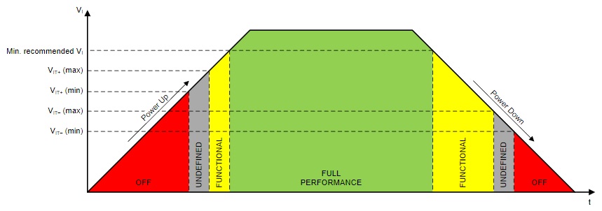
To implement UVLO, a small, low-power comparison circuit within the converter compares the input voltage to a preset threshold. It puts the supply into quiescent mode until the threshold is crossed. A small amount of hysteresis ensures that the UVLO does not chatter around the threshold. So, for example, the supply will turn off when the input drops below 5.0 V but will not turn on until the rising voltage reaches 5.5 V
What is Overvoltage Protection (OVP)?
Although a supply or converter is designed to produce a fixed DC-output voltage normally, an internal failure in the supply may cause this voltage to rise and possibly damage the load to which the supply is connected. This failure could be due to a short circuit in a wiring harness, the failure of a passive component, or the failure of an active device such as a MOSFET. Regardless of the source, it is undoubtedly undesirable by itself, especially if it can also damage the load. OVP is a function that monitors the output versus an internal reference and short-circuits that output if the voltage rises above the threshold.
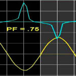
The circuit that monitors and trips is called a “crowbar,” supposedly so named because it has the same effect as placing a metal crowbar across the output. A properly designed crowbar is both simple and functions independent of the supply itself (Figure 2).
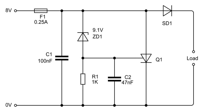
There are two kinds of crowbars: one where the crowbar, once tripped, will only be reset if the power I tuned off; and one where it will reset itself once the output-voltage fault is cleared. The second one is useful when the condition that tripped the crowbar is due to transient rather than a hard failure in the supply. While most supplies now come with a built-in crowbar, many vendors offer a small, separate crowbar circuit that can be added to an existing supply if needed.
What is thermal overload protection?
By its nature, any power supply generates heat because it is less than 100% efficient. Even an efficient supply generates a potentially troublesome amount: a 100-W collection that is 90% efficient still dissipates 10 W, which is very capable of warming up an enclosure. For this reason, the supply must be designed with sufficient active cooling (such as a fan) or passive cooling (achieved by convection and conductive cooling).
But what happens when the fan fails, the air-flow path is blocked, or another heat source is introduced into the enclosure? The supply may exceed its temperature rating, which severely shortens its life and may even cause immediate malfunction. The solution is a circuit within the supply that senses the temperature and puts the supply into a quiescent mode if it exceeds a preset limit. As with OVP, some thermal cutoffs automatically allow the supply to resume operation if the temperature drops, and others do not. Which approach is “better” depends on the nature of the application and usage cycle.
These are the primary internal protection mechanisms in a power supply or converter. There are also “defenses” against external events and malfunctions, usually provided outside the supply or as add-on adjuncts.
Reference
Texas Instruments SLVA769, “Understanding Undervoltage Lockout in Display Power Devices”
[…] Brownout vs. Blackout: What’s the Difference? | NEC Co-op Energy (neccoopenergy.com) Basics of power-supply self-protection – Power Electronic Tips Power Problems – Critical Power Supplies FAQ-MEAN WELL Switching Power Supply Manufacturer […]