
In qualitative terms, power factor is a measure of the congruency of voltage and current ac waveforms imposed by a load on the power mains. Ignoring the relative phase of the two waveforms, the apparent power (S) is the simple product of the waveform amplitudes, S = V × I.
Limiting our focus for now to sinusoidal waveforms without significant harmonic content, we can separate the apparent power into its real (P) and reactive or quadrature (Q) components.
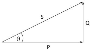
The power factor (PF) is given simply as PF = cos(θ). Notably, resistive loads operate with unity power factor (θ = 0; S = P). These include ye olde incandescent lamps and non-inductive heating elements — nearly a redundancy — that comprised much of the original load to the first ac mains-power grids.
The most common cases of purely sinusoidal deviation from unity power factor derive from inductive components. For example, the no-load component of the apparent power a utility delivers to mains-connected transformers and inductive motors is reactive.
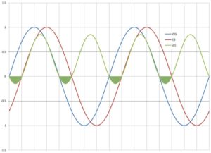
The power that does real work derives from the in-phase component. The reactive power — the integral of the filled-in regions of S(t) in the accompanying figure — simply sloshes back and forth between the utility energy source and the load, but that’s not a lossless process: Dissipation through the power distribution network derives primarily from I2R heating, which is real and independent of the relative phase of voltage and current waveforms. Also of concern to the utility, the total delivered current for loads operating at PF < 1 is greater than for unity PF loads by a factor of ![]()
.
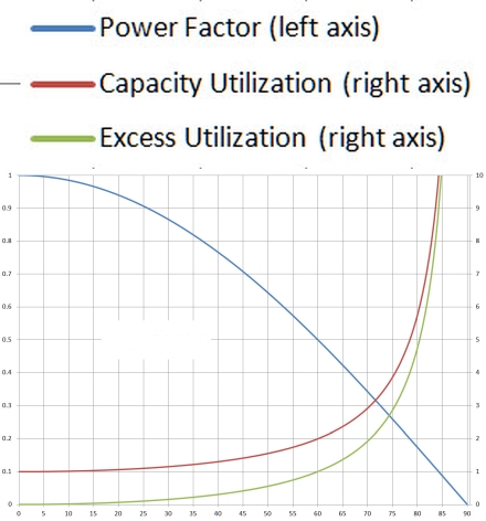
The reciprocal of the power factor, then, is a measure of source and grid current-capacity utilization for a given load. For loads that are close to unity — say 0.9 or better — the penalty for imperfect PF is modest, but as the power factor decays further, the increase in excess utilization rapidly accelerates.
From the customer’s perspective, you might wonder why any of this matters. After all, utility meters for all but large industrial customers measure only the real power. Large industrial sites are often equipped with two meters, one that measures real energy use and the other, often referred to as a VAR meter, which measures the power feed’s quadrature term. So if you’re not operating a large industrial site and not being billed for excess capacity utilization, why care?
Well, there are several reasons: Utilities base their rates, in part, on their real costs so, you’re paying for the losses. Excess utilization is essentially a preventable downgrade of infrastructure. Sooner than would otherwise be the case, rate payers or tax payers (same people, just different pockets) will be chipping in for capacity upgrades or living with over-extended grids and generation capacity. Does the phrase rolling blackouts sound familiar, California?
Excess utilization isn’t a problem that ends at the power meter: It extends to the premise wiring too. Although customer power meters only measure the in-phase component and, therefore, can’t detect excess capacity use, circuit breakers only monitor current, irrespective of relative phase. So within the premises, loads with poor power factor degrade branch capacity in the same way they degrade grid infrastructure, except branches start with already low current-carrying capability: 12-A continuous on a 15-A breaker at unity PF.
Power factor is defined as the cosine of the lead or lag angle of a power feed’s current waveform with respect to the voltage waveform. This definition reflects the historical origins of power factor issues, which lie in the reactive loads presented primarily by electric-powered machinery.
In practice, however, modern power infrastructure, in-premises wiring, and protection devices throughout face power-factor degradation more from the effects of nonlinear loads than from reactive ones. Recall that any deviation from congruency between current and voltage waveforms reduces the power factor. So, in addition to relative phase error, waveform distortion is a major contributor to the problem.
By Fourier analysis we can decompose periodic non-sinusoidal waveforms into a series of harmonically-related sinusoids. In terms of useful power delivery, the harmonics do not add to the real (in-phase) component. So essentially, the THD (total harmonic distortion) —- typically expressed as a root-sum-square percentage relative to the fundamental —- contributes to the quadrature or reactive component, degrading the power factor:


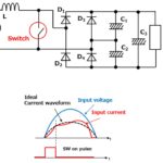
Take, for example, the line current waveform at the input of a full-wave-rectified power subsystem’s front-end, which drives the charging upstroke portion of the filter capacitor voltage. Depending on the size of the filter capacitor and the magnitude of the load current, the forward conduction interval through the rectifier covers only a small portion of each half cycle. Even at high load, where the conduction angle is largest and the current waveform comes closest to congruency, the current waveform for a full-wave rectified ac power front end is rich with odd harmonics.
PFC (power-factor correction) methods based on capacitive compensation that, for decades, were effective on large synchronous motors don’t work for loads that produce significant THD in the current waveform. These include both rectifier-input electronic power supplies and variable-speed-drive electric-powered machinery, despite the many similarities the latter has with synchronous-motor applications.
The problem in both cases is that the dominant power factor term derives from THD in the current waveform, not phase error. The simple traditional PFC structures for standard ac motors shunt the input with a capacitive reactance that drops with increasing frequency,
While the capacitive reactance decreases monotonically with rising frequency, the harmonic amplitudes in the current waveform are not. Furthermore, the most common damaging effect of poor power factor caused by THD isn’t excess capacity utilization but I2R heating, which is unaffected by current-waveform phase. I2R heating doesn’t just needlessly dissipate power in the power distribution infrastructure. It shortens the useful operating life of transformers and other apparatus.
Last, high THD in the current waveform can cause nuisance tripping of protective devices, which creates far greater and more immediate disruption than wasting a few kilowatts or shortening the life of some grid apparatus.
Now we can calculate PF compensation for commonly arising load conditions. Consider that an apparent power vector, S, represents the arithmetic product of the voltage and current magnitudes, which we can deconstruct into its real (P) and reactive or quadrature (Q) components. We calculate the resulting power factor as

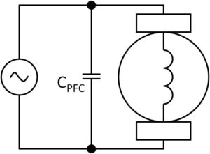
Consider the case of ac motors and other inductive loads, which simply impose a lagging current waveform on the power source relative to the applied voltage. For these cases, simple power-factor correction is possible by connecting an appropriate-sized capacitance across the inductive load.
We can measure the true power with a proper wattmeter and, by measuring load current, calculate the apparent power. From these data the reactive power Q and required compensating capacitance CPFC is simply
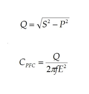
where f is the line frequency and E is the RMS line voltage.
The capacitive PFC method is appropriate for inductive loads driven by a fixed-frequency sinusoidal source. It is decidedly inappropriate for most variable speed drives that, for example, exploit switching motor-control methods. The current waveform’s large high-frequency harmonic content in these applications can generate destructive I2R heating in the parasitic ESR (equivalent series resistance) of shunt capacitors, particularly at resonance. You can find numerous online photographs of charred remains in systems that misapplied PFC capacitors.
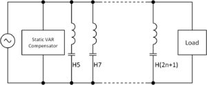
One PFC arrangement appropriate for industrial loads in excess of 10 kW uses passive shunt harmonic filters formed in any of several topologies including the simple series LC. Each tap is tuned to a different odd harmonic, but the overall reactance at line frequency is capacitive.
The design of passive multi-stage harmonic filters is challenging in part because of the complex system-impedance curve and harmonic content across the bandwidth of interest. Given the size and cost of the components and the load-specific design requirements, the manufacturer of the load apparatus most often supplies the passive harmonic filters for PFC.
Another method, active PFC, has become widely used because it stably corrects for essentially arbitrary current-voltage waveform incongruencies within its current capacity and bandwidth. As such, active PFC is highly adaptive to changing loads—an important factor in highly efficient power trains to support complex electronic systems. Additionally, active PFC designs take advantage of high-speed switching and, thereby, greatly reduce the size, cost, and weight of reactive components for a given current capacity compared to other PFC methods.
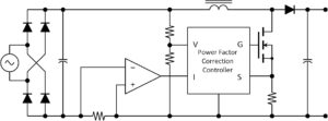
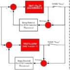
One basic active PFC architecture samples the input voltage from a full-bridge rectifier through a resistor divider to provide a waveform reference for current processing. A resistor shunt in the return leg lets the controller monitor the total current. A high-speed PWM controls the power MOSFET, generating a sawtooth current through the inductor to impose an average current proportional to the voltage thereby forcing the current waveform to match the input voltage. The input capacitor serves as a high-frequency filter. The output bulk capacitor stiffens the output to drive downstream dc-dc power converters.
Specific control methods vary among controller manufacturers as do architectural and performance details. All, however, boast excellent power-factor-correction performance over a wide range of loads and operating conditions.


Thanks. great info