
The first FAQ in this series looked at the various hardware options for implementing digital power. Part two took a deep look at the PMBus/SMBus communication protocol for implementing digital power configuration, control, and monitoring. This FAQ will delve into the system-level benefits of using digital power converters with PMBus communication.
PMBus can benefit the design and production of AC/DC power supplies and DC/DC converters. It can bring performance benefits to complex electronic systems that employ distributed power architectures with numerous point-of-load (POL) non-isolated DC/DC converters. And it can deliver benefits to users of power module ICs that integrate the PWM controller, inductor, power MOSFETs, and passive components into a tiny package for high-efficiency power conversion. The following discussion presents three perspectives on the benefits of using digital power converters with PMBus communication from the Excelsys division of Advanced Energy Industries, Analog Devices, and Renesas Electronics.
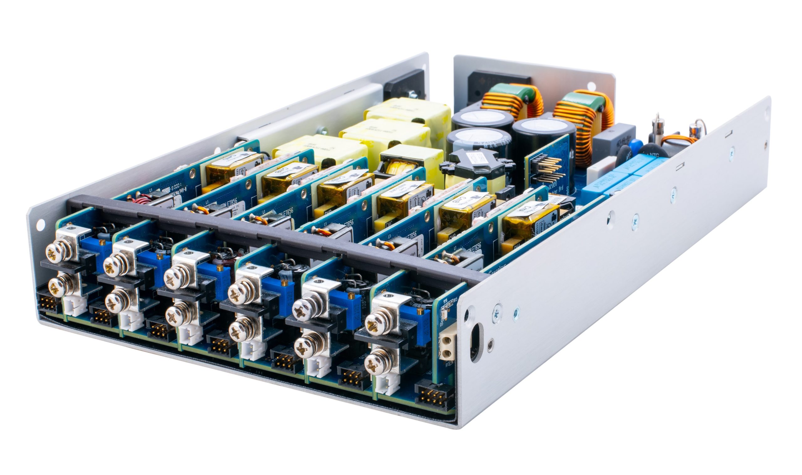
AC/DC power supply product life cycle benefits
When developing a new electronic system, the Excelsys division of Advanced Energy Industries finds that PMBus can be beneficial throughout the product lifecycle for concept development, design, development, debug, production, maintenance, and even wear out. During the concept stage, when testing the feasibility of the power supply, PMBus can support fast iterations of voltages and currents that can be changed on the fly. It enables designers to try different hardware configurations with maximum flexibility and makes documenting the results easy and efficient.
PMBus supports power supply configuration and the establishment of the needed margins when finalizing the design parameters. It makes it easy to make peak measurements for each device on PMBus, including readings during motor starts and equipment cycling. It also supports the measurement of corner performance for low voltage and low current conditions.
During the design finalization and debug process PMBus can check the sequencing of various loads, measure operating margins, check operation over temperature, can be used to explore possible improvements in margins and sequencing timing, and can help identify any overload or out of specification/tolerance conditions.
And during the active product lifecycle from production to maintenance and through the wear-out stage, PMBus can provide several benefits. PMBus can be used for end-of-line testing during production to verify that the configuration is built correctly. It can measure variability in production and help with the qualification of alternate components, checking for shifting operating parameters and helping to ensure product consistency.
During the operating life of the power supply, PMBus can be used to monitor the system and make sure it continues to operate within specifications. It can help monitor for early signs of wear and identify needs for preventative maintenance, thereby reducing the cost of ownership. And at end of life, PMBus can provide the data needed to predict when wear out will occur and support the timely replacement of power supplies before catastrophic failures occur.
Digital power use models in a distributed power architecture
Analog Devices has produced a comparison of two common digital power use models:
- Configure and Deploy
- Monitor and Act
One of the most important PMBus command sets is storing and restoring settings between operational and non-volatile memory. When combined with commands for changing operational memory (behavior), they support the Configure and Deploy use model.
- Configure and Deploy
Most manufacturers of PMBus products have a GUI tool that can communicate with their products via the PMBus. The fundamental use pattern is to configure all the registers of the PMBus devices on a bus and store their values in non-volatile memory. Then when the system is powered or reset, all devices load operational memory from non-volatile memory during startup.
The fundamental strength of this model is its simplicity. Tools can absorb much of the PMBus complexity by organizing data, templates, and project reuse. A secondary advantage is lower cost because no “extra” devices are required to manage the bus.
The fundamental weakness of this model is the forfeiture of all the capability of the PMBus during normal operation. All the devices must react autonomously during abnormal conditions, such as faults, but the flexibility is limited and not coordinated. The same is true at reset. All devices must startup autonomously. To overcome this limitation, many devices have additional IO pins that allow devices to communicate between them without PMBus. A common approach is to use open-drain signals between devices. Often, there are three pins:
- SYNC
- RUN
- GPIO
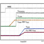
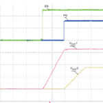
The SYNC pin is used to establish a common time-base at reset. This allows accurate time correlation for sequencing on/off events. The RUN pin enables all devices to reset simultaneously, either from an external gate or from the devices themselves. GPIO is typically a fault output and fault input. This allows a fault from one device to propagate to other devices. These pins are not part of the PMBus specification but are necessary for the Configure and Deploy use model to work as a system.
- Monitor and Act
The most flexible use model requires a PMBus controller that is active during the system’s operation. The Alert Pin is typically connected to an interrupt pin on the controller. When there is a fault, the controller reacts to the interrupt by getting the address of the faulted device, querying conditions via PMBus, and taking action to correct the problem or power down rails.
The controller is also used for telemetry. The data may be used to predict failure, measure power consumption, or debug rare faults. The controller will also set up all the rails at reset.
The Monitor and Act model is highly flexible, but development is more complex. Development costs can be minimized if the software can be reused on multiple designs, but the increased hardware cost will remain a consideration.
System benefits of digital power and PMBus
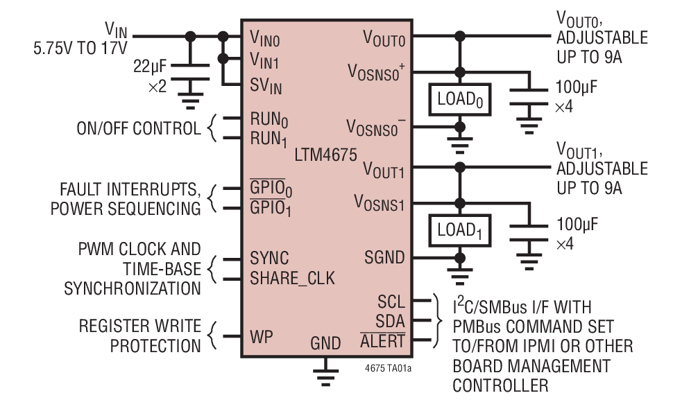
Power distribution systems for data servers, network equipment, and base stations often need many voltage rails, which are required to sequence or track other rails to properly bias microprocessors, microcontrollers, ASICs, FPGAs, and any other digital logic ICs. The use of PMBus capable encapsulated DC/DC power modules can bring several benefits to these complex systems:
- Enables intelligent power management to maximize system performance
Using SMBus and PMBus-enabled devices for power conversion provides flexibility and control that is not possible with traditional analog power systems. Using digital power, the adjustment of output voltages, power sequencing, and synchronization of multiple voltage rails can be easily managed through a host controller via the SMBus and PMBus protocol.
In addition, a digital power solution provides multiple methods of reacting to a fault for system monitoring. Over-current, under-current, over-voltage, under-voltage, and over-temperature faults and warning thresholds can be configured and adjusted throughout the product’s lifecycle. Operating temperatures can be monitored to regulate the cooling fans dynamically to lower the system power consumption.
- Reduces development time of system products
As a product design moves through various phases, changes in the design can occur, including adding a power rail, more current on a rail, or the requirement for tighter transient response. Usually, this would require the redesign of the power distribution system. Still, with digital power, a new voltage rail can be easily added to the power management system using the industry-standard SMBus. The new rail is integrated into the monitoring, sequencing, margining, and fault detection schemes. The digital power IC for the new rail is provided with its SMBus address. There is no need to reprogram or add more standalone power management ICs because of the additional voltage rail.
Digital power allows system designers to reduce their time on the power system and concentrate on designing key product features and functions, reducing product development time and R&D cost.
- Reduces system BOM costs while improving reliability and product lifespan
With digital power, many system management and power control functions can be implemented with firmware instead of using extra analog and power control devices. System designers can use the same device for each voltage rail and make changes to the operation of the device without having to make hardware changes. As a result, the total BOM cost can be reduced. With fewer components and digitally managed protection features, system products can have greater reliability and a longer lifespan.
- Enables compact system design and product upgrade within the same chassis
The increasing demand for high-speed data, voice, and video communication has driven datacom and telecom service providers to upgrade their network equipment with faster and more reliable products with more features. While the speed and system functions increase, the available space is limited. This means that the system designer needs to add more function circuits to the board and reduce the area occupied by power supplies. Many power monitoring and sequencing control functions can be easily implemented with firmware with digital power. As a result, the PCB area for power is reduced, and more functional ICs can be added to the same board area.
This three-part FAQ series took a deep and wide look at digital power technology, starting with “Digital power conversion – how does that work?” followed by considering “Digital power management and PMBus™ moving into the future.” This final installment reviewed the benefits designers can expect to enjoy when deploying systems using software configurable power systems and PMBus communications.
References:
Digital Power Management, Analog Devices
PMbus in System Applications, Excelsys
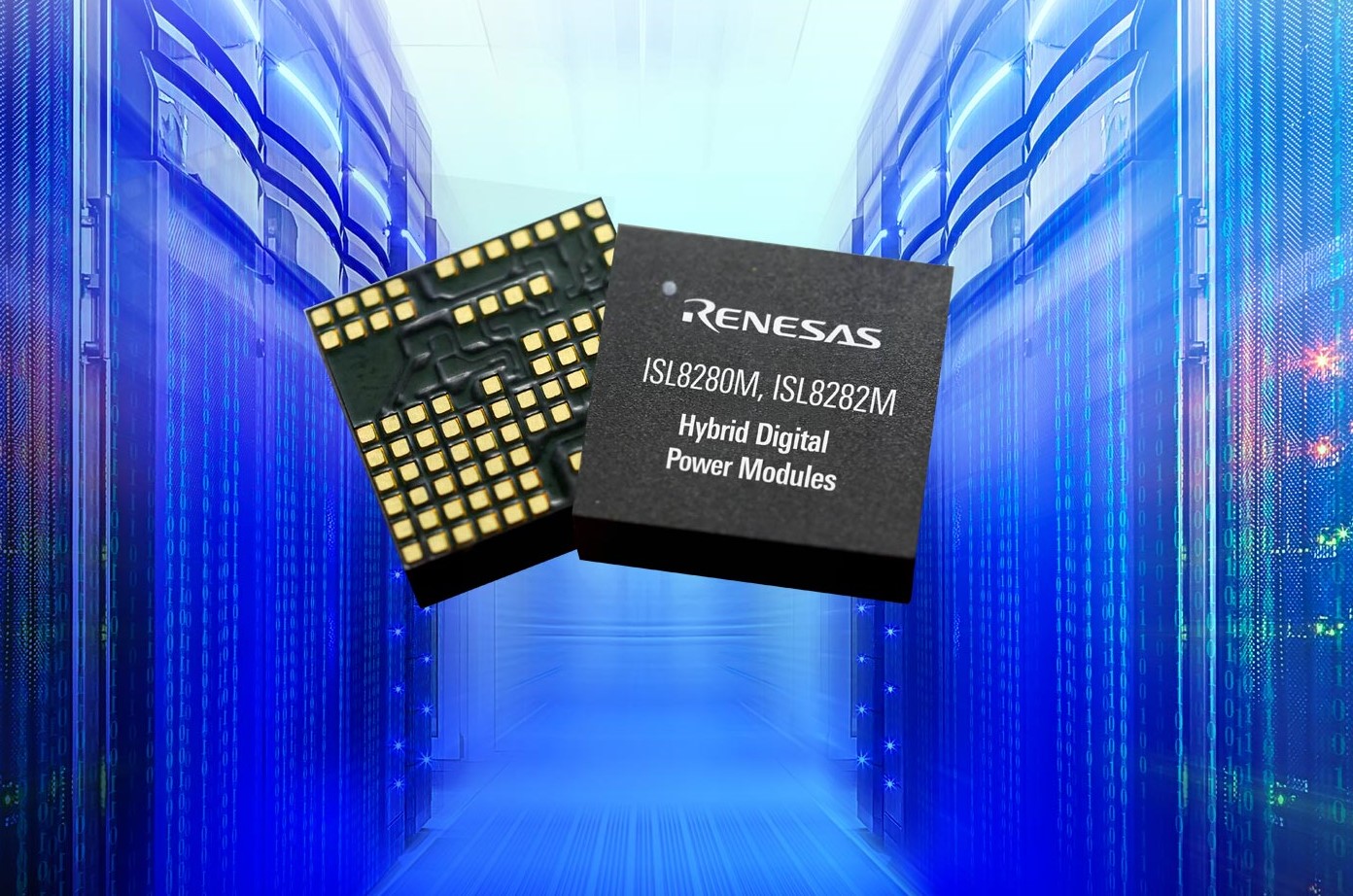
The Benefits of Using Digital Power Modules, Renesas Electronics
Using PMBus™ for Improved System-Level Power Management, Texas Instruments


Leave a Reply