by Jim Earley, President, Premier Magnetics
Electromagnetic interference (EMI) and radio frequency interference (RFI) are natural byproducts of switching power supplies. Much of this noise arises as a direct result of the large voltage swings caused by short-duration charging and discharging in the power supply circuitry. Common mode noise, which is generated through the power line and returns to the source through some type of ground path, is a key problem as well.
Power supply designers can use several filtering techniques to control such EMI/RFI. One of the more effective techniques is to place a common mode choke (CMC) after the full-wave diode rectifier. This helps meet numerous rules and regulations that define electromagnetically compatible (EMC) power supplies. In the U.S., the Federal Communications Commission (FCC) is responsible for regulating EMI emissions. Part 15 of FCC rules specifies that any spurious signal above 10 kHz be subject to regulation. It also specifies that radiated emissions must be controlled between 30 MHz and 1 GHz, while conducted emissions must be controlled in the frequency band between 450 kHz and 30 MHz.
The regulatory agency overseeing EMC in Europe is the International Special Committee on Radio Interference, or CISPR. The committee’s third edition of CISPR, Pub 22, (known as CISPR 22 or EN55022) defines those regulations and has been adopted by much of the European community. Other countries have developed their own regulations as well. The Federal Republic of Germany, for example, requires compliance with its own VDE 0871 or VDE 0875 regulations. Canada sets limits similar to the FCC Part 15 in its C108.8-M198 rules. Generally speaking, all current regulations cover frequencies in the 10 kHz to 30 MHz range.

Both the FCC and CISPR standards divide electronic equipment into two classes. Class A equipment encompasses devices designated for commercial, business and industrial environments. Class B devices include personal computers, calculators and similar devices typically used in residential settings. In general, the standards define more severe constraints for Class B devices because they are more likely to sit close to radio and TV receivers in the home. Typically, Class B limitations are about three times more restrictive than Class A limits (~10 dB). But there are a few differences. CISPR 22 requires certification over a 150 kHz to 30 MHz frequency range for conducted emissions rather than the 450 kHz to 30 MHz range specified by the FCC. In addition, the FCC specifies limits for frequencies above 1 GHz; the CISPR does not.
Beginning in the 1990s, regulatory agencies began harmonizing the different RF emissions standards for digital devices. The revised rules let electronics developers certify equipment by simply demonstrating that their device complies with either the FCC Part 15 or CISPR 22 regulations. One caveat: The same standard must be used for both conducted and radiated emissions. Today, conducted and radiated emission limits specified in FCC Part 15 and in CISPR 22 are within a few dB of each other over prescribed frequencies. So designers can use either regulation without compromising the accuracy of the measurement or certification process. The FCC retained its standard for emissions above 1 GHz, but adopted the test distances specified in CISPR 22. It is also important to note that FCC limits are given in microvolts while CISPR limits are measured in dB-microvolts, so the units must be converted for a direct comparison.
Common-mode chokes
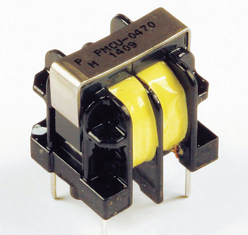
Many electronic circuits need CMCs to filter out noise that is common to, or coupled to, the power and network lines. A CMC features two identical windings with the current in each winding flowing in opposing directions. The live and return currents are of the same magnitude because they are from the same power source. But the direction of the magnetic flux lines created by the current flowing into the first winding opposes the flux lines created by the return current in the second winding. These two magnetic pluses cancel each other out to create a theoretical net flux of zero.
As a result, the choke presents little inductance or impedance to the differential-mode currents. This means the CMC core will not saturate because of the amplitude of the main currents. High-frequency noise currents, however, are of much lower amplitude. They will see a high impedance because of the common inductance of the windings and will be severely attenuated or filtered out.
It is possible to use discrete inductors and capacitors in front-end filtering instead of CMCs. Discrete components do offer a small cost advantage. In many cases, however, that cost advantage may be more than offset by a need for flux bands or shields on the main transformer. A flux band, basically a circumferential copper shield around the entire transformer, can complicate the design. It is often left floating, but may be connected to the secondary ground. If connected this way, the transformer may need reinforced insulation between its primary and secondary for safety reasons. If the transformer uses an air gap on its outer limbs, a fringing flux from the gap causes severe eddy current losses in the flux band. Additionally, the ends of this band should be soldered together.
All in all, avoiding use of a CMC may incur not only a more complex transformer, but also a need for additional inductors and/or capacitors to filter the power lines. This design strategy drives up system cost and complexity. For example, adding a flux band or shield to a typical 30- to 50-W SMPS transformer will boost component cost by 20 to 30%. Moreover, this approach may make FCC compliance more difficult. It often takes relatively powerful power-line filters to meet conducted noise specifications. Yet safety regulations limit the size of the capacitors fitted between the supply line and ground plane. This limitation can often result in filtering that doesn’t cure the common-mode interference problem it tries to address.
Designers who opt to add capacitors for filtering can face additional issues. Electrolytic capacitors added after the rectifier diodes are more likely to fail from overvoltage, heat or other factors. Film capacitors are also undesirable because of UL/CE requirements and their loss of capacitance over time.
To reduce common mode noise, CMCs whose ferrite cores are toroid-shaped are the most effective. Their continuous, unbroken magnetic flux path maximizes magnetic coupling between windings and minimizes leakage inductance. However, the core material, the high number of windings and the use of a plastic mounting base make toroids more expensive than other CMCs. Furthermore, isolation between windings is typically limited to withstand less than 1.5 kV, which may limit their use in some applications.
A combination of efficient filtering and low cost can come from CMCs with ferrite cores shaped like an E or a U. These devices offer isolation between the two windings up to 3 kV, which helps meet UL and other safety agency requirements while ensuring FCC compliance. In general, E cores can handle higher power levels and can provide a higher level of inductance. The U core is slightly less expensive than an E core because of its simpler geometry but has less inductance capability.

Designers can also use this style of CMC as an output filter. Long cable runs that are connected to a safety ground act like antennas when common mode currents flow through them. A CMC filter can limit radiated EMI on long output cables where the output return is connected to safety earth ground.
When selecting CMCs, there are a few points to keep in mind. Most CMC line filters use standard ferrite material, but the grade of ferrite in the choke may depend on the inductance required. Higher inductance requires a more permeable core. However, designers needn’t specify the number of wire turns on the chokes; the number of turns is standard for a given part number. The user need only select a choke that meets inductance, current and rated voltage requirements. Circuit designers must only concern themselves with the choke’s rated current, VA rating, inductance and package options.
Finally, the physical size of the CMC package is generally determined by the amount of electrical current it carries, (which primarily determines the wire size), plus the inductance needed.
Resources
Premier Magnetics
www.premiermag.com


It is a very informative blog, Lee. I didn’t know much about the Choking off EMI/RFI in off-line switchers but your blog updated me lots of information about EMI/RFI filters.
Great job!