
by Derick Stephens, KEMET Corporation
Selecting capacitors for decoupling and filtering in power circuits may seem like a basic chore for electronics designers. Getting it right, however, can critically influence reliability and longevity, but is complicated by the fact that parameters tend to change with factors such as the temperature and operating frequency. Proper attention should be paid to capacitor selection, taking advantage of the technical resources now more widely available online to simplify and accelerate the process.
Capacitor ripple current capability
In power-conversion circuits, such as AC/DC power supplies, DC/DC converters, and even DC links, capacitive filters are needed to counter fluctuations that cause instability. Success is usually manifested as a lack of noise present in the DC power output and free of disturbances transferred into nearby circuitry.
The fluctuations in question are superimposed on the ideal, stable waveforms. Interference can arise from a variety of sources. One common source of noise is the rectification of AC; the resultant DC output from a rectifier usually has some amount of the source AC content superimposed on it. Switching regulators of all types create a certain amount of ripple when performing its primary function. Good designs usually try to mitigate this ripple as much as possible, but it can’t be completely eliminated. As a general principle, the capacitors are placed in the circuit to absorb and discharge the energy associated with these fluctuations on a continuous basis, and so minimize the peaks and troughs.
As a result of this action, the capacitor continuously passes a varying current. This current is called ripple. Although ripple current is the inevitable result of the capacitor performing its required task, it causes undesirable I2R heating as it passes through the Equivalent Series Resistance (ESR) that is associated with any capacitor. If the I2R effects exceed the capacitor’s ability to dissipate heat, its temperature can rise and hence adversely affect reliability. At the least, the component lifetime may be affected according to the Arrhenius Law, which states that lifetime is reduced by half for every 10°C increase in operating temperature. More extreme heating, exceeding the specified maximum temperature, can destroy the capacitor by causing drying or boiling of liquid electrolyte, cracking of ceramic capacitors, or ignition. A heatsink could be used to limit the temperature rise, if the application space and weight constraints allow. On the other hand, calculating the ripple current and understanding the properties of suitable capacitors can help to achieve the most space-efficient and cost-effective solution.
The capacitor datasheet indicates a ripple current rating that broadly describes the maximum ripple the device can withstand. This can be used as a guide, with the understanding that it is evaluated under controlled conditions. These are defined in standards such as EIA-809 or EIA/IS-535-BAAE, although there is some ambiguity in these documents. To help engineers understand the issues surrounding ripple current, KEMET has published an article, Ripple Current Confusion, in its online technical library (ec.kemet.com), which describes these standards and their applicability in detail. Discrepancies in the measurement of ripple current capability prevent easy direct comparisons between the ripple current capabilities of different manufacturers’ capacitors. Datasheet figures are useful, however, for comparing products from the same manufacturer.
Calculating ripple voltage and current
To choose the right capacitor for the input filter of a switching regulator, for example, the capacitance needed to achieve a desired voltage ripple can be calculated, if the operating conditions of the regulator are known. When the capacitance is calculated, a candidate component can be identified, and the ripple current determined from the known ESR. This ripple current must be within the capacitor’s ripple current handling capability, if the device is to be suitable for use. This is where selection can become difficult, because both ESR and capacitance are known to vary with temperature, operating frequency, and the applied DC bias.
The capacitance can be calculated using the equation (from TI Application Report SLTA055)
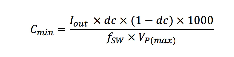
Where CMIN = minimum capacitance required
IOUT = output current
dc = duty cycle (usually calculated as dc=Vout/(Vin*Eff))
fSW = switching frequency
VP(max) = peak-to-peak ripple voltage
Assuming, for example, a regulator with 12v input; 5v output; 2amp output; 85% efficiency; 400kHz switching, and an allowable input ripple voltage of 65mV:
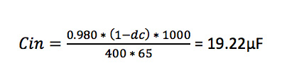
Note that the chosen device must provide this value of capacitance at the regulator operating frequency of 400kHz.
The rms value of the peak-to-peak ripple voltage can be calculated from the equation:
Vrms=Vpp*1/(2*√2)
The ripple current in the capacitor can then be calculated by applying Ohm’s law, if the capacitor’s ESR is known.
A note of caution
At this point, the variability of capacitor properties, according to operating conditions, must be considered. Most engineers understand the temperature stability issues of class II/III dielectrics. Fewer understand the magnitude of capacitance loss due to the operating frequency and the applied voltage.
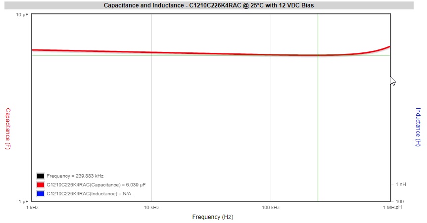
Recall that 19.22µF, as calculated earlier, is the capacitance required at the regulator’s operating frequency of 400kHz. The ESR must also be known at this frequency, to calculate the ripple current.
If a capacitor with nominal capacitance of 22µF and voltage rating of 16V is chosen, as the nearest standard value above 19.22µF, the actual capacitance of this device is 5.951µF at 400kHz, as shown in figure 1, and the ESR is 3.328mΩ. The resulting ripple voltage and current can be calculated as 210mVp-p/74.23mVrms, and 22.3A respectively. These are significantly greater than the target ripple voltage and maximum allowable ripple current for the capacitor.
The value of simulation
Every manufacturer of Class ii components will advocate simulating the component behavior allowing for application voltage, temperature and frequency. KEMET’s K-SIM online electrical parameter simulator lets engineers assess capacitor performance under a variety of operating conditions. it is available in the KEMET Engineering Center, alongside the ripple-voltage calculator mentioned earlier and other tools and support information including technical notes and application guides.
Using K-SIM, engineers can quickly analyze one or multiple capacitors that may be suitable for the application they are working on. Among the various features, K-SIM can display impedance and ESR, or capacitance and voltage versus operating frequency, and also predict temperature rise depending on ripple current and frequency. An on-screen cursor helps ensure accurate measurement. K-Sim also allows capacitor S parameters to be evaluated, and SPICE models and STEP files obtained for components of interest.
With the aid of this tool, a 47µF X5R capacitor was identified, with the same case size and voltage rating as the 22µF/16V device selected earlier. The capacitance value is 19.9µF at 400kHz under the applied DC bias, and thus restricts the peak-to-peak ripple voltage to 63mV. Hence Vrms = 22.27mV. This capacitor’s ESR is 3.246mΩ at 400kHz, suggesting the ripple current is 6.86A, which is below the maximum for the device.
Conclusion
The issue of ripple current can be challenging to analyze and to predict accurately under expected circuit-operating conditions. When left unchecked the heating caused by ripple currents can adversely affect the life of the capacitor. Nevertheless, proper assessment of the ripple voltage and current is vital, to ensure a power circuit like a switching regulator will deliver the required performance over its intended lifetime. Online tools and information provide valuable help to calculate the capacitance needed and accelerate component selection.
ripple current of 1 component with 47uf capacitance is 110mA, however for the other component with same capacitance value has a 115mA, also they have 25V of rated voltage and with 20% tolerance. Does it mean that these 2 components is the equivalent or similar?. they only differ in ripple current.
TIL comparing phone chargers is a worth hunt