
It may seem a bit mundane but choosing ceramic capacitors can cause some problems and confusion. Ceramic capacitors have taken over from aluminum electrolytic capacitors and tantalum electrolytics in a lot of cases and even film capacitors but there are pitfalls. For example, the very low ESR (equivalent series resistance) of ceramic capacitors can cause instability with some voltage regulators, particularly ones with low dropout voltages. The Texas Instruments TPS7350 is unstable with low ESR so you could end up having to add a series resistor to make the ESR of your capacitor higher. This is one of the graphs from the TPS7350 datasheet which illustrates the problem.
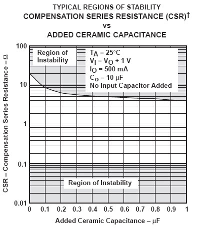
You could use a solid tantalum electrolytic capacitor instead of ceramic, but they are now fairly expensive and you still need to be careful when you choose one – too high an ESR can also result in instability. If you cannot avoid using such regulators then you need to be careful in your capacitor choice and it is always a useful precaution to include the provision for a series resistor when using a ceramic capacitor with a low dropout regulator.
With ceramic capacitors you have a choice of dielectrics. They are usually called low, medium and high K or Class 1, 2 or 3 but nowadays you are more likely to come across notations such as C0G, NP0 or Y5V. These are not actually descriptions of the dielectric but of its characteristics. Low K or Class 1 capacitors are temperature compensating capacitors although the most common is NP0. This is NP zero – the zero denoting the temperature coefficient. So, it is fairly stable with temperature, usually +/-30ppm/C. N220 would have 220ppm/C negative temperature coefficient and P100 would have 100ppm/C positive temperature coefficient but mostly people want a temperature stable capacitor. Absolute tolerances of Class 1 capacitors is also pretty good – down to 2% or even 1%.
Capacitors with low relative permittivity (Class 1) will become physically quite large when you need a high value so higher permittivity helps keep size and cost down – hence the Class 2 and 3 types. These might be described such as Y5V or X7R but these are actually really definitions of the upper and lower temperature range and temperature coefficient. So X7R is for -55 to +125C operation and +/-15% variation over the operating temperature range. Wikipedia has a good description under “Ceramic Capacitor”. Some of the capacitors have very poor initial tolerance (as much as +80%/-20%, like some electrolytic capacitors) and very poor temperature stability. Their main use is just to have a large capacitance where you don’t care too much about the “quality” of the capacitance such as for a decoupling capacitor. They can have other undesirable characteristics such as dielectric absorption and voltage dependent capacitance. This makes them unsuitable in certain circuits such as filters or high quality amplifiers where they can cause distortion.
Dielectric absorption can manifest itself as a “bounce back” in a capacitor voltage when it has been discharged. I have also seen it as a drop back in the voltage a capacitor has been charged to when the charging source is removed in a sample and hold. The easiest way to imagine the effect is to consider the capacitor to consist of two (or more) capacitors connected by a resistor. If you simulate such a scenario, you can observe the effect for different circuits.
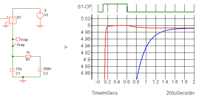
This simulates the 10uF capacitor as having an extra 200nF connected by a 1k resistor. The capacitor is charged to 5V through the switch which has a 1 ohm ON resistance. When the switch is opened (with a very high OFF resistance) the capacitor voltage drops – red trace. This is because the 200nF capacitor hasn’t completely charged (blue trace) so when the charging source is removed the two capacitors balance their voltage through the 1k resistance. Note that this is a simulation of how the effect manifests itself rather than a description of the internal makeup of the capacitor. In fact, more complex models of capacitors involve multiple capacitors and resistors in order to better simulate the actual characteristics.
The effect on discharging is shown below.
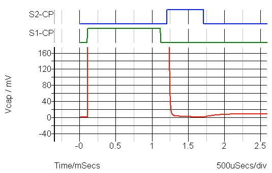
Here the capacitor is charged to 5V then discharged. The discharge switch is controlled by the blue trace and when that switch is turned off the voltage on the capacitor “bounces back” by 10mV. This is because the 200nF capacitor has not fully discharged so again, the capacitors balance their voltage. Note that the times involved can be very long. A Wima test for dielectric absorption waits for 15 minutes before checking the residual voltage after discharge.
KEMET have an interesting document called “Why that 47 uF capacitor drops to 37 uF, 30 uF, or lower” which has a good description of some of the problems with various capacitor types and dielectrics.
I haven’t actually touched on other capacitors such as class X and Y or various film capacitors but that will have to wait for another time. Ceramic capacitors seem to be king for most applications although that is mainly because of cost and size rather than them necessarily being the “best” for some applications.
Leave a Reply