
Energy efficiency in power supplies can be as much about the inductors as about the circuit topology. A few simple calculations can prevent unpleasant surprises.
CHRIS HARE,
LEONARD CRANE
COILCRAFT, INC.
In high frequency dc-dc converters, inductors filter out the ac ripple current superimposed on the dc output. Whether the converter steps the voltage down – buck – or steps the voltage up – boost – or both up and down – SEPIC – the inductor smooths the ripple to provide a pseudo-dc output.
Applications with batteries can extend battery life by improving the efficiency of the entire power supply circuit, and inductor efficiency is often a major part of the design. Careful consideration of inductor efficiency can mean the difference between having your battery work when you need it and having it die in the middle of an important task.
Inductor efficiency is highest when the combination of core and winding losses are at a minimum. Therefore, highest efficiency comes from selecting an inductor that provides sufficient inductance to smooth out the ripple current while simultaneously minimizing losses. The inductor must pass the current without saturating the core or over-heating the winding.
It can be fairly complicated to accurately predict an inductor’s core and winding loss. Core loss depends on several factors, such as peak-peak ripple current, ripple current frequency, core material, core size, and turn count. The required ripple current and ripple current frequency are application-dependent, while the core material, core size, and turn count are inductor-dependent.
The most commonly-used equation to characterize core loss is the Steinmetz equation:
Pcore = K(f)x(B)y
Where Pcore = power loss in the core, W; K, x, y = core material constants; f = frequency, Hz; and B = flux density, T. This equation shows that core loss depends on frequency f and flux density B. Flux density depends on ripple current, so both are application-dependent variables. The equation also shows that the core loss is inductor-dependent, where the core material determines the K, x, and y constants. Note flux density is also a function of the core area (Ae) and the number of turns (N), so core loss is both application-dependent and inductor-dependent.
By comparison, dc winding loss is simple to calculate:
Pdc = ldc2 × Rdc
Where Pdc = dc power dissipated, W; ldc = effective dc (rms) value of the inductor current, A; and Rdc = dc resistance of the inductor winding, Ω.
AC winding loss is more complicated and may include the effects of increased resistance at higher frequency caused by both skin and proximity effects. ESR (effective series resistance) or ACR (AC resistance) curves may show some of the increased resistance at higher frequency. However, these curves are typically made at low current levels, so they do not capture current-dependent (core) loss. They are also subject to possible misinterpretation.
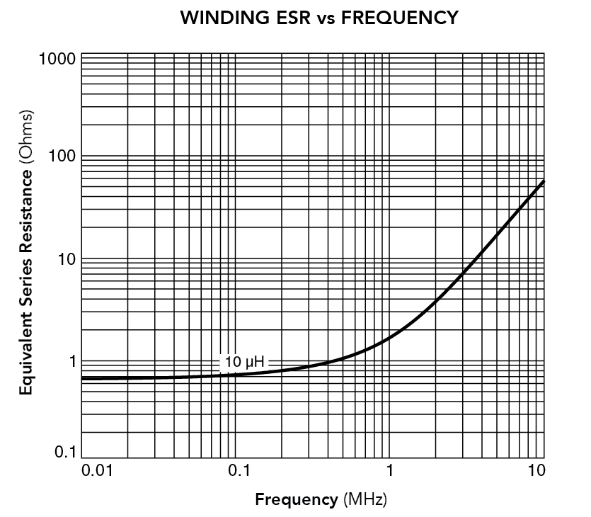
For example, consider the ESR vs frequency curve in the accompanying figure. An initial observation is that the resistance looks high above 1 MHz. This behavior would strongly suggest that the inductor not be used at that frequency because of the high loss from ESR. However, it has been observed that parts with curves like this have performed well in actual converters – much better than the curves would suggest.
Consider the following example: Assume a converter must provide an output of 5 V at 0.3 A (1.5 W). We use a 10-µH Coilcraft inductor with a typical ESR vs frequency as in the accompanying figure. If the converter operates at 250 kHz, the graph shows that the ESR, which includes both ac and dc resistance, is approximately 0.8 Ω.
For a buck converter, the average inductor current equals the load current, 0.3 A.
We can calculate the loss in the inductor:
l2R = (0.3)2 × (0.8) = 0.072
0.072 ÷ 1.5 = 0.048 ~ 5%
Thus approximately 5% of output power lost in the inductor. However, if we were to run the same converter at 5 MHz, we can see from the ESR curve that R is between 10 and 20 Ω. If we assume R = 10 Ω, the power loss in the inductor should be:
l2R = (0.3)2 × (10) = 0.9
0.9 ÷ 1.5 = 0.60
Thus 60% of the output power is lost in the inductor! Based on this simple example, it would seem obvious that a designer should not choose a component like this.
It has been observed that converters, in fact, often realize better performance than the ESR curves predict. The following explanation illustrates why.

The nearby figure shows a simplified version of a possible buck converter waveform, with continuous conduction. The ripple current is relatively small compared to the average current.
Assume the ripple current peak-peak is about 10% of the average current. From the previous example this means Idc = 0.3 A and Ip-p = 0.03 A. To predict the inductor losses correctly, current must be separated into two components. For the low-frequency or dc loss, we use the low-frequency resistance (effectively Rdc), which we can see from the graph is 0.7 Ω. The current is the rms value of the load current plus the ripple current. In this case the ripple current is small, so the value is approximately equal to the dc
load current.
‘
To get the total loss, we must add low-frequency loss to the high-frequency loss, which is I2R. In this case the R is the ESR and the I is the rms value of the ripple current only.
Approximate rms ripple current = lp-p ÷ 2√3 = 0.03 ÷ 3.464 = 0.0087 A. At 250 kHz the ac loss would be: I2R = (0.0087 A)2 × (0.8 Ω) = 0.00006 W.
I2R = (0.0087 A)2 × (10 Ω) = 0.00076 W.
Therefore, at 250 kHz, we predict the total inductor loss is 0.063 W + 0.00006 W = 0.06306 W. We see that operating at 250 kHz predicts only slightly more loss (less than 1%) than predicted simply by Rdc.
Now, let’s look at the same example at 5 MHz. The low frequency loss is still the same 0.063 W. The ac loss calculation must use the ESR, which was previously estimated at 10 Ω:
Low-frequency loss = ldc2R = (0.3)2 × (0.7) = 0.063 W
So, the total inductor loss at 5 MHz is 0.063 W + 0.00076 W = 0.06376 W.
This loss is more significant, about 1.2% greater than Rdc loss, but is not nearly the 0.9 W originally predicted by multiplying the ESR by the entire load current. Also, this example is not exactly fair, because we wouldn’t use the same inductor value at 5 MHz as we would at 250 kHz. We would use a much smaller L and therefore we would get a much smaller Rdc.
In summary, the inductor loss must be calculated by a combination of the Rdc and ESR. Losses will be reasonable for a continuous current mode converter in which the ripple current is small compared to the load current.
In typical applications, ripple current is kept to approximately 40% of the load current or less. Regardless of ripple content, ESR curves do not capture current-dependent core loss at higher current. And total inductor loss determines the overall inductor efficiency.
Therefore, inductor manufacturers optimize inductor efficiency by selecting low-loss materials and designing inductors for minimal total loss. The use of rectangular “flat” wire may provide the lowest Rdc in a given size to minimize dc loss. Improvements in core materials have led to inductors with low ac core loss at high frequency, resulting in higher inductor efficiency.
For example, Coilcraft has just released the XEL series of molded power inductors that are optimized for high-frequency, high-peak-current applications. These inductors are designed for soft-saturation, while giving the lowest ac loss at frequencies of 2 MHz and higher.
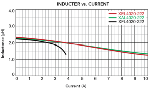
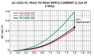
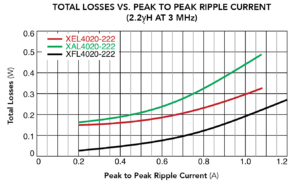
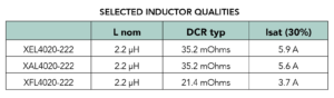
The nearby graph of inductance vs current characteristics is for the 2.2 µH value in the XEL, XAL, and XFL series. The XEL and XAL series are clearly the best choice for holding inductance at currents of around 3 A or higher. Another nearby graph compares the ac loss and total loss of the same inductors at 3 MHz. Although the XFL inductor has the lowest total power loss, the new XEL inductor has lower total loss than the XAL and is therefore the best choice for high-frequency power converter applications that must withstand high peak current.
To speed the design process for engineers selecting inductors, Coilcraft has developed tools that calculate measurement-based core and winding loss for each possible application condition. The results from these tools include current-dependent and frequency-dependent core and winding loss, eliminating the need for requesting proprietary inductor design information, such as core material, Ae, and number of turns, and the need to perform hand calculations.
If you already know the inductance value and current ratings required for your application, you can enter this information directly into the Power Inductor Finder. The results include core and winding (total) loss and saturation current ratings for each inductor, to verify that the inductance will remain close to the design requirement at the peak current condition for your application.
The tool may also be used to graph the inductance-vs-current behavior to compare traditional hard-saturating inductors to soft saturation types.
Designing for highest efficiency requires selection of inductors with the lowest total loss at application conditions. Calculating total loss can be complicated, but these calculations are built into Coilcraft power magnetics tools, making selection, comparison, and analysis as simple as possible.
REFERENCES
Inductor Performance in High Frequency dc-dcConverters, Len Crane, Document 470-2, 2015
XEL, XAL, or XFL? – Making the Best Choice
Leave a Reply