
by Steve Griffiths, Manager of Technical Sales and Marketing, Ametek, Dynamic Fluid Solutions Business Unit
It pays to do a back-of-the-envelope thermal analysis before cranking up a CFD program for power electronics.
Power electronics can generate a lot of heat, so much so that many modern power supplies incorporate fans or blowers to keep temperatures down. The task of cooling is often complicated by packaging constraints. The real estate available for power circuits can be pretty small. So the thermal analysis of these circuits generally calls for use of a computerized fluid dynamics package or other software.
Nevertheless, it can be convenient for circuit designers to know in which ballpark they are playing before cranking up a thermal analysis program. When working with cooling fans, a few calculations can show how much cooling to expect from a fan given the temperatures involved.
To begin, the use of a fan basically improves the heat transfer coefficient of the components that are transferring heat to the surrounding air. To figure out the requirements for the fan, the designer must determine the amount of air necessary. A good approximation for how much air is required comes from the mass flow relationship:
Eq. 1: q = w Cp ∆t
where q = the amount of heat the air absorbs, btu/hr; w = mass flow of air, lb/hr.; Cp = specific heat of air, btu/lb°F; and ∆t = temperature rise of the air in °F. This equation yields the following relationship which applies more directly to the forced air cooling of electronics
Eq. 2: Q = (178.4*ti*W)/(∆t*P)
where Q = airflow needed, ft³/min; ti = inlet temperature, °R (°F + 460°); ∆t = temperature rise across the equipment, °F; W = power the equipment dissipates, kW; P = barometric pressure at the air inlet, in. of Hg. Here it is assumed that the air picks up all the heat to be dissipated. In other words, the relationship ignores conduction and radiation as well as natural convection effects on the external surfaces of the equipment.
For standard conditions of 70° F and 29.92 in. Hg, Equation 2 reduces to the familiar
Eq. 3: Q = (3,160*W)/∆t
A good rule of thumb for cooling is that a 15° F temperature rise is probably enough. Planning for a higher temperature rise tends to oversize the air-moving device.
The only way to move air around electronics is to create a pressure drop. The situation is analogous to causing the flow of electrical current by applying a voltage across a resistance. The resistance to flow is defined by an equation having the form:
Eq. 4: ∆P = K ρ Qn
where ∆P = pressure drop, in. H2O; Q = airflow, f3/min; K = a constant determined by the qualities of the system; n = a constant that depends on the type of flow; ρ = density of air, lb/ft3. The constant n will assume a value from 1 to 2 depending on whether the flow in the system is completely laminar (n = 1) or completely turbulent (n = 2). For most electronic equipment, n will be nearly 2. You can assume this value for calculation purposes unless there is data showing it to be otherwise.
The air flow path through electronics is typically complex. So pressure drop calculations do not yield easily to the simple fluid flow equations. If there is a physical prototype available, it is generally best to test the equipment for its flow resistance qualities.
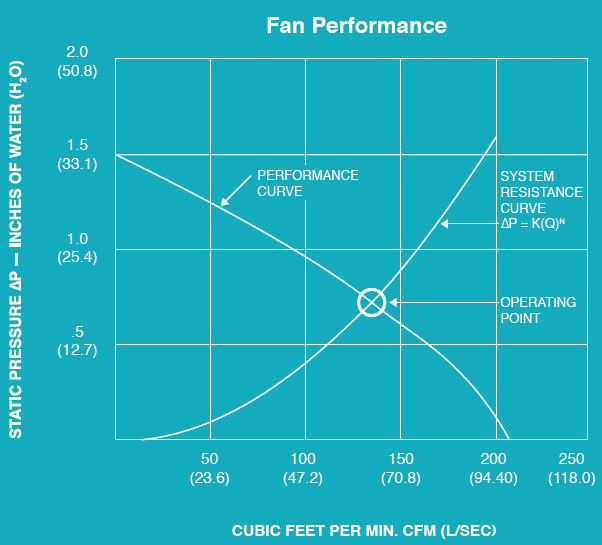
Suppliers of cooling fans now typically provide fan performance curves (actually a family of curves) covering the full range of performance with flow rate on the X axis and static pressure on the Y axis. This format provides a quick snapshot of how a given fan model and size behaves.
Static pressure is the resistance to airflow (friction) caused by the air moving through the air handling system—pipes, ducts, hoses, filters, hood slots, air control dampers or louvers. In the case of electronics, there are usually few air handling components to worry about. But the point is that static pressure should include the pressure drop through all of the ductwork on the inlet and outlet of the fan, plus the pressure drop through any filters, control dampers and so forth, or through any other system components that restrict airflow.
Thus, to determine what kind of fan can cool the electronics, the designer must calculate a system air resistance curve (equation four) for the application at hand and plot this equation on the family of fan performance curves. Then the air flow required is that at the intersection of the performance curve and the resistance curve. At this operation point, the pressure available from the fan to force air through the assembly is equal to the pressure necessary for that flow.
However, designers are concerned with the amount of power needed to accomplish cooling. The factors influencing air-mover operating efficiency are the flow and pressure range, the operating speed range, the motor powering the air mover, and any electrical device that modifies the power supplied to the motor. These variables influence the efficiency at specific operating points as spelled out by
Eq. 5: A = (Q*∆P)/6,350
Eq. 6a: S = (T*N)/5,252
Eq. 6b: S = A/Nf
Eq. 7: I = S/Nm
where A = air horsepower, hp; Q = air flow, ft3/min; ∆P = pressure drop, in. H2O; S = motor shaft horsepower, hp; T = motor torque, lb-ft; N = motor speed, rpm; Nf = fan or blower efficiency; I = motor input horsepower, hp; Nm = motor efficiency.
The overall efficiency of the cooling system No is just air horsepower divided by the power the motor consumes, or A/I. No can also be expressed as the product of blower efficiency, motor efficiency and the efficiency of the cooling device, usually denoted Ne:
Eq. 8: No = Nf*Nm*Ne
To maximize efficiency, and minimize noise, the air mover generally is operated at 50% or more of its peak efficiency. The best efficiency point, BEP, is usually in the middle two-thirds of the flow rate range.
There are a few other points that are important when fans or blowers cool electronics. The vast majority of cooling equipment used for electronics are axial fans. They use fan blades to draw air in and discharge the air in the same axial direction. The other main type of cooling equipment is a centrifugal blower. A centrifugal blower has a scroll rather than a fan blade or propeller. It draws air into its inlet, through the scroll wheel, and discharges it at 90° out through a housing outlet.
Finally, it should be pointed out that these calculations assume the use of standard air, which is 70° F, 29.92 in. barometric pressure (at sea level) and 0.075 lb/ft3. Of course, air density changes with temperature and/or barometric pressure variations (at higher altitudes). Usually, applications in cooling electronics can ignore these effects, but manufacturers typically supply temperature and/or altitude conversion factors that can be used in making the corrections to standard conditions if the planned environment warrants it.
Leave a Reply