Engineers are all familiar and comfortable with voltage sources such as batteries or ac/dc supplies. The function of a voltage source, represented by a simple symbol is clear: Provide as little or as much current as needed (up to a maximum current limit) at a given, defined voltage; this voltage value may be fixed or variable in the design.
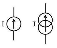
Voltage sources, of course, have a functional complement: the current source. Its role is to provide a preset amount of current at whatever voltage is required (again, up to a maximum voltage, called the compliance voltage and analogous to maximum current of a voltage source). The current source is needed because there are components and systems which must see a specific current value, rather than a specific voltage value.

It may seem that a current-based source is unnecessary, as the designer can always adjust the voltage to provide the desired amount of current. This is true in some ways, as current and voltage are linked by Ohm’s law (V = I × R). But using a voltage source in this way yields an inconsistent source of current. The issue is whether the current or voltage is the independent versus the dependent variable. In other words, whether you need the current to follow the voltage, or the voltage to follow the current.
Where are current sources are needed?
A good example of an application needing a current source is a series string of LEDs. LEDs provide their light output as a result of the current through them and are specified by a “current-versus-output” curve. A typical LED requires 20 mA for its nominal output, so the string can be powered by a 20-mA current source. Even if another LED is added, the same current source is used.
That would not be the case if a voltage source was used instead. Assume each LED has a forward voltage drop VF of 1.5 V. Suppose the current to the LEDs came from a voltage source, with a current-limiting resistor sized to allow only 20 mA of current after accounting for the sum of these drops. In this case, the LED string would work properly. But if an LED was added, or one shorted out, the current from this voltage source would no longer be 20 mA: It would drop with the addition of an LED or rise if one shorted.
In contrast, when using a true current source, the number of LEDs in the string does not matter. The maximum number of LEDs which can be handled is a function of the compliance voltage of the current source, which must exceed the sum of all the diode drops. Also, the circuit does not need the current-setting resistor in series, as the current source inherently establishes the correct value.
Another widely-used application of the current source is in industrial process-control loops, to convey analog readings from sensors as well as send analog control signals to actuators. The control industry has used a simple 4-to-20 mA current loop for many years, where 4 mA represents the minimum sensor output/actuator setting and 20 mA is used for the maximum.
Why use a current loop here rather than a voltage signal? Two reasons. First, if a wire in the loop breaks, the current drops to zero, a condition which is immediately and easily detected. In contrast, a break in a wire conveying a voltage signal is not easily recognized and may provide false voltages which look valid.
Second, a current source and its loop form an inherently low-impedance topology, while a voltage source is a high-impedance configuration. Therefore, the current loop is much less susceptible to picking up noise from nearby EMI/RFI sources, whereas noise can easily be picked up by the voltage arrangement.
A basic current source can be built from a voltage source and a resistor in series sized to limit the current to the designated value, using Ohm’s law. This approach is sometimes used in inexpensive applications where accuracy and consistency are not important, because any change in the load will change the current. Also, the resistor dissipates power, which limits run time (if using a battery) and adds to thermal load.
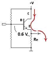
A better way starts with a transistor in a common-emitter configuration, where the load through the collector is a function of the base-emitter current by the well-known equation:
IC = β × IB,

where IC = collector current; β = transistor gain and is a function of the transistor design; IB = base current set by the base-circuit design. This approach is used as the core of many current sources, with various enhancements to maintain stability and accuracy. Current sources are available in ICs which supply a few milliamps of current, or 20 mA for industrial loops, all the way up to modules which provide many amps with compliance voltages in the tens or hundreds of volts.

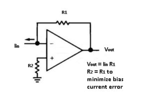
When used with a current source, LEDs “convert” the current to light. In many circuits, however, there is a need to transform the current to a voltage to be used by the rest of the circuitry (amplification, filtering, and A/D conversion, for example). Fortunately, it is simple to build a current-to-voltage converter (called an I/V converter). The current is put through a resistor, and an op amp senses and amplifies the voltage across the resistor. The value of the resistor is calculated to provide the desired scale factor. For example, if the maximum loop current is 20 mA and the desired voltage scale goes to 10 V, a 500-× resistor is needed.


Leave a Reply