
A common situation is when you may have more than one possible power source to power some electronics. For example a mains AC-DC adaptor or a battery may be used to power an electronic device. In the past the simple solution was to use a DC power connector with a built in physical switch such as this one from Lumberg.
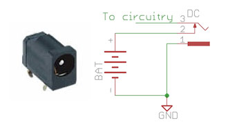
When the DC plug is inserted it breaks the power from the battery to the circuitry so the power then comes from the external DC power source. While that sounds fine, it has a major disadvantage which mean it is not used much nowadays. The power to the circuitry from the battery will be broken before the power from the external DC supply is connected. This is inevitable to prevent the external DC power source connecting directly to the battery but it also means that your equipment will lose power briefly and with a microcontroller based system that will cause a reset. If the plug is inserted slowly to just the right point you can even break the power so the equipment gets no power indefinitely.
Most systems now use the center pin for positive whereas it is the edge connection which is broken with these sorts of connector which is also inconvenient.
A simple alternative is a couple of diodes, preferably Schottky diodes.

The circuitry will be powered by whichever diode has the higher anode voltage and the switch (if present) isn’t used. When there is no external DC power the battery will power the electronics and when the external DC power is applied, that will power the electronics provided it is higher than the battery voltage. However, now we have lost a diode volts drop. While that probably doesn’t matter for the external power supply, we don’t really want to be wasting so much power on a battery operated system from the battery supply.
If the battery is rechargeable and the external DC adaptor is for charging the battery, one solution is to feed the external DC power through the charging circuit to the battery. This is quite an efficient system, depending on the nature of your charge circuit. Some charge ICs will provide charge source switching as well, such as the LTC4075.

The intention with the LTC4075 is that your circuitry is powered directly from the battery and the LTC4075 provides charge control and also the selection of either the USB port or external DC adaptor for the charge source, based on which has the higher voltage.
Another option is to use the so called “ideal” or “perfect” diodes. Linear Technology do a range of power switching devices (“PowerPathTM Controllers”) such as the LTC4411/4412 or the LTC4357 which is a controller using external MOSFETs for high voltage/high current switching. There are also very high current devices from a company called Perfect Switch. These integrate the controller and MOSFETs into a power module. They behave like a couple of diodes but can switch up to 300A and with a voltage drop of only 30mV at maximum current. Like the Linear Technology devices, this extreme performance is achieved by using comparators and some logic to switch over MOSFETs so the voltage drop is only that of a very low ON resistance MOSFET rather than the relatively fixed voltage drop of a true diode.
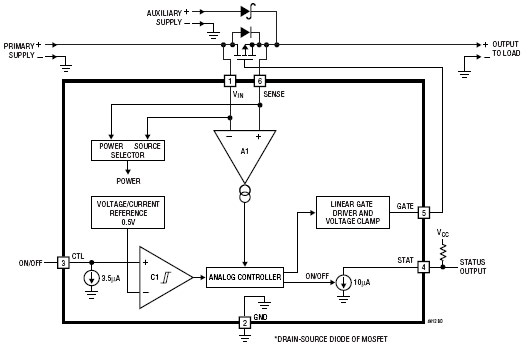
In the case of the LTC4412, quiescent current is low, around 11µA, and by having the MOSFET external you can use it for very high current switches. It is tiny – a 6 pin TSOT-23 package (although your MOSFET will increase total area). The voltage drop across the MOSFET is typically 20mV – read the datasheet for a full description of the operation as the controller tries to maintain that 20mV drop. You can also use a second MOSFET rather than a diode for the auxiliary supply for lower loss – again, see the datasheet for more details.
I have 4 400w solar panels for charging a 3600w Ecoflow Delta Pro with extra smart 3600w battery.
The pro has a limit of 150v and 15amps. I can only use 3 at a time but would like option of being able to turn Delta Pro off and switching from 2 batteries on one array
maybe with panels one facing SW and other facing S to other array with panels facing SW and W.
Is there a device that excepts 2 different solar arrays and outputs to the inverter battery using CT60 connectors that you can manually switch from one array to the other with the battery inverter turned off eliminating the need to manually disconnect the Mc4 connecters at the panel charge wires?
I am puzzled by your first two schematics, isn’t ‘1’ supposed to be connected to the circuitry, ‘3’ to GND, and ‘2’ to the GND side of the battery?