
When current goes through the primary winding of a theoretical (ideal) transformer, it generates a magnetic field which induces a voltage across the secondary winding. Connecting a load to the secondary causes an AC current to flow in the load. However, a physical transformer is far from ideal and includes parasitic resistances, inductances, and capacitances, which are non-linear and complex effects.
The non-ideal nature of physical transformers results in the need for relatively complex specification documents when using these devices. The following discussion is not a design guide, but is intended to provide a basic theoretical framework to assist in understanding the specifications of RF transformers for real-world applications.
The figure below shows a commonly-used model for a two-winding transformer. On the primary side, the winding resistance is represented by Rp, the leakage inductance by Llk, magnetizing inductance by Lm, core loss by Rc, and self-capacitance by Cp. The secondary winding resistance is Rs, the secondary self-capacitance is Cs, and the primary to secondary capacitance is Cm.
The elements of this transformer model are used for several purposes—specifying components, identifying problem design areas, and circuit simulation. However, this apparently simple model is complicated by the fact that all of the resistors and inductors of the model are nonlinear functions of either frequency, or excitation level, or both. The capacitors can also exhibit minor nonlinearities, but are further complicated by the fact that the lumped elements shown are a very crude approximation to the true multiple interwinding capacitance effects that really exist in the component.
Due to their non-ideal characteristics, these devices operate with a limited bandwidth, have insertion loss, a maximum power rating, and exhibit other frequency-, temperature- and power-dependent performance.
Non-ideal materials
Not only is the physical implementation of RF transformers less than ideal, the wires and cores from which they are fabricated are also less than perfect. At RF frequencies, the skin effect of wires can become a design consideration for transformers. In the skin effect, high-frequency ac currents occur mostly on the outer layer (skin) of the wire increasing the ac resistance, reducing its effectiveness as a conductor.
And the capabilities of magnetic core materials are a major source of the non-ideal performance of physical transformers. There are several types of core materials such as powdered metals, ferrite ceramics and air that allow optimization for various application requirements.
Many powered metal materials are used today including iron, carbonyl iron, molypermalloy (MPP), high-flux Ni-Fe, KoolMU, nanocrystalline, and so on.
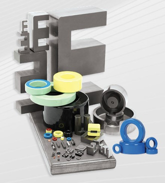
Powder core materials are made from discrete particles of ferromagnetic powder. Prior to being formed into a core, the particles are covered in a thin layer of electrically insulated material to ensure electrical isolation of each particle. The particles are then compacted under high pressure to form the core geometry.
The electrical insulation between particles enables the materials to be used at high frequency. Finer particles allow operation at higher frequencies, as the eddy currents are mostly restricted to within the individual grains. The insulation also forms a distributed air gap throughout the core material, giving the material the ability to maintain inductance linearity with a DC biasing field.
Ferrite ceramic materials can be engineered with a wide range of parameters. As ceramics, they are essentially insulators, which prevents eddy currents, although losses such as hysteresis losses can still occur.
Air core devices can be wound on a plastic or ceramic form in addition to those made of stiff wire that are self-supporting and have air inside them. Air core coils generally have much lower inductance than similarly sized ferromagnetic core coils but are used in RF circuits to prevent energy losses resulting from core losses. The absence of normal core losses permits a higher Q factor, so air core coils are used in high-frequency resonant circuits, up to a few megahertz. But the losses from the proximity effect and dielectric losses are still present.
Making the best of a non-ideal situation
As discussed above, physical RF transformers are non-ideal devices made from non-ideal materials and components. Several fabrication methods and transformer structures have been developed to mitigate the impact of the various design challenges and help to optimize RF transformer characteristics for the needs of specific applications. That will be the focus of the second article in this series.
References
High-Frequency Power Transformer Measurement and Modeling, Ridley Engineering, Inc.l
How RF Transformers Work and How They are Measured, Minicircuits, Inc.
Powdered Metal Materials, Micrometals, Inc.,
Skin Effect, Wikipedia
Magnetic Cores, Wikipedia
Leave a Reply