
Power converter modules can simplify equipment design, but engineers may still need to look at EMC emissions and input-surge filtering.
Gary Bocock, XP Power
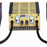
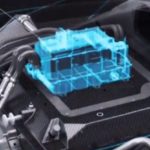
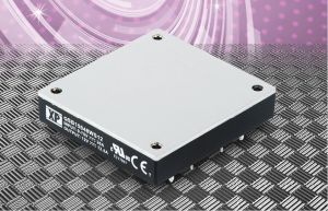 Baseplate cooled power converter modules, also known as bricks, provide building-blocks for integrating power conversion into end equipment. These high-density power modules find use in outdoor sealed enclosures, transportation and defense applications where their rugged construction and conduction cooling come in handy. They also are widely applied where high-density forced-air-cooling and compact size bring benefits.
Bricks provide the building blocks for low-risk bespoke power supplies. These supplies are often designed by end-equipment designers using support and application notes from the manufacturer. But module manufacturers themselves use these modules as bases for custom supplies that have low development costs, and which can be brought to market quickly.
However, baseplate-cooled converters are component-level rather than drop-in products. They generally require additional design work and components to handle electrical safety, thermal management and electromagnetic compatibility (EMC). They target both dc and ac input applications. Their typical input ranges are designed to cover battery and dc vehicle supplies as well as higher voltage, rectified or power factor corrected (PFC) ac supplies.
The industry has developed standard sizes for these modules termed quarter bricks, half bricks and full bricks. Power ratings up to 600 or 700 W can be realized in a standard 2:1 input full brick. However, power density drops as the input range widens to 4:1, 8:1 or even 12:1. The trend toward wider input ranges has come out of efforts to accommodate several different battery chemistries and from attempts to standardize system design for multiple power platforms.
Baseplate-cooled converters with ac input are also available providing ac to low-voltage dc conversion, or as PFC modules with high-voltage outputs (usually around 400 Vdc) to drive high-input-voltage dc/dc bricks. Most of these ac-input products also require additional design and components, including high-voltage electrolytic capacitors and components for EMC. However, a few do not. An example is the ASB110, 110-W complete ac/dc full-brick supply from XP Power, which requires only thermal management and includes all other parts.
Thermal management
Thermal management is a key for power bricks designed to be baseplate-cooled. The brick is configured so power-dissipating components, such as the power semiconductors and transformer, are thermally bonded to the baseplate. The baseplate temperature must always stay below a maximum operating temperature. The thermal resistance of the cooling scheme must be such that the module stays below the maximum temperature spec while powering the load.
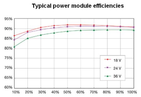
The power dissipated (in watts) can be determined from the module efficiency specification under the worst-case operating conditions. But it is important to consider the both the operating load and lowest input voltage applied rather than the data sheet headline efficiency.
Once the efficiency at the worst-case operating point is established, the waste power to be dissipated as heat is calculated as

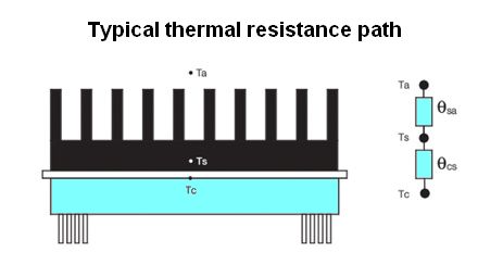
where Ef is efficiency in percent, Pout is output power in watts. A simple equation, θ = ∆T /Q, determines the thermal resistance required for operation. Here ∆T is defined as the difference in degrees Celsius between two reference points; θ is thermal resistance in °C/W, and Q is the heat flux or power in Watts passing through the two points. The thermal resistance, θcs, from the case to heatsink is typically 0.1 ⁰C/W when using a thermal pad or grease.
Use of this equation allows the calculation of junction temperatures using a thermal circuit analogous to that for an electrical circuit. The thermal resistances can be treated mathematically the same as electrical resistances. Thermal resistance to the flow of heat from the power module to the ambient air surrounding the package consists of two thermal resistances: that from the case to the heatsink, and that from the heatsink to the ambient interfaces. The two resistances can be summed to give an overall thermal resistance from power module to ambient:
![]()
where TC = maximum power supply temperature; TA = ambient temperature, PD = power dissipation, and θCA = case-to-ambient thermal resistance.
The thermal resistance of the heatsink-to-ambient depends heavily on available airflow; in convection-cooled applications the heatsink will be much larger than in a comparable power system with forced air or liquid cooling. When using multiple bricks connected to a common heatsink or cold wall, the sum of the dissipated power from each brick in the system, under worst-case conditions, determines the overall maximum thermal resistance allowable.
Heat sinks and other thermal management measures aren’t the only components baseplate-cooled modules need before they switch on for the first time. Other additions include those for reverse polarity protection and control of noise emissions, as well as for protection against spikes and surges. Noise mitigation typically takes the form of a capacitor network, inductors, and surge-suppressing components. And fusing is a must to head off catastrophic failures from short-circuiting the supply.
The power module data sheet and application notes will specify the values of the components required. It is up to the design engineer to implement them, following good design practices for any creepage and clearance requirements, and minimizing parasitic inductance for EMC compliance.
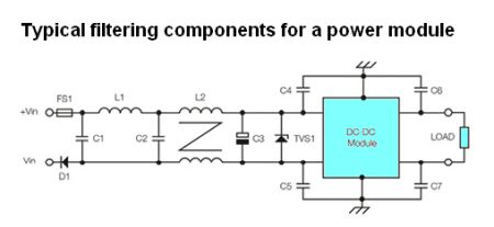 A nearby circuit diagram illustrates typical components found in power supply circuits to handle noise, filtering, and other issues. Here, FS1 protects against an input short-circuit failure. L1, C1 and C2 form a pi filter to mitigate differential noise created by rapid changes in current through the power switching stage. Similarly, L2, C4 and C5 form a common-mode filter to mitigate noise created by the rapid changes in voltage in the power stage. C3 presents a low impedance source for the power converter switching current demand, and TVS1 is a bi-directional transient surge suppressor to protect against spikes and surges. C6 and C7 reduce output common mode noise. An additional differential filter may be added at the output for applications that require extremely low noise.
In general, the decoupling capacitors (C4, C5, C6 and C7) should be as close as possible to the pins and chassis connection to the baseplate to keep the PCB traces as short as possible. The input electrolytic capacitor C3 and transient voltage suppressor TVS1 should sit physically close to the input pins of the module. And tracks beneath the power module should be avoided.
A limited number of application-specific filter modules are available to handle the abnormal surges found in dc input transportation and defense applications. These generally also require a few additional components for full compliance.
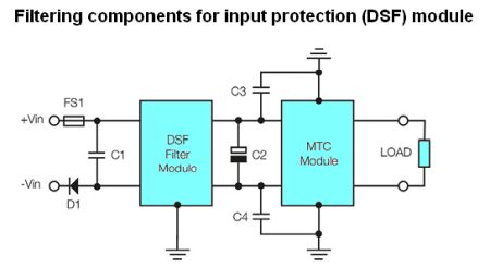 A near-by diagram shows the case where an input protection (DFS) module contains all the necessary active surge protection circuits and the filter inductors necessary for a 28-V nominal military vehicle supply. Here, C1 completes the differential filter stage. C3 and C4 make up the common-mode filter stage. C2 provides a low-impedance source for the MTC series dc/dc converter.
A PFC module for an ac input power system requires similar EMC components, and a high-voltage (450 Vdc) electrolytic bulk capacitor (C6) is 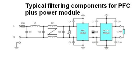 also necessary. The system hold-up or ride-through requirements determine the value of the bulk capacitor.
Some ac input solutions combine the PFC and dc/dc sections into one brick, with connections made available for the bulk capacitor. There are additional requirements for ac input systems regarding creepage and clearance distances between line and neutral, and between line and neutral and earth. These creepage and clearance distances are outlined in the end application’s relevant safety standard.
Of course, the added inductors, capacitors, and other components must remain within their thermal limits. The electrolytic capacitors must exhibit a service life acceptable for the mission profile of the end equipment. Insulating thermal pads may help conduct heat away from the inductors to the equipment cold wall. Other components often mount on the reverse side of the PCB away from any higher-temperature parts.
The best manufacturers of these high-density baseplate-cooled brick converters provide application information and EMC data to support their products. They also maintain experienced applications engineers to support equipment designers during the design and compliance testing phases. And they typically offer pre-compliance testing against common industrial, communications, transportation and defense EMC standards.
Module manufacturers also have seen myriad application-specific custom designs; they can pass on lessons learned from these invaluable experiences. All in all, having the module manufacturer design and produce a bespoke brick-based power system eliminates the need for additional design and testing resources so the OEM can focus on the core system design.

They generally require additional design work and components to handle electrical safety, thermal management and electromagnetic compatibility (EMC).