• Skip to primary navigation
  • Skip to main content
  • Skip to primary sidebar
  • Skip to footer

Power Electronic Tips

Power Electronic News, Editorial, Video and Resources

  • Products
    • Power Supplies
    • AC-DC
    • DC-DC
    • MOSFETS
    • Power Management
    • Battery Management
    • RF Power
    • Resistors
    • Capacitors
    • Magnetics
    • Transformers
  • Applications
    • LED Lighting
    • Rack Mount
    • Wireless
  • EE Forums
    • EDABoard.com
    • Electro-Tech-Online.com
  • EE Learning Center
    • Design Guides
      • WiFi & the IOT Design Guide
      • Microcontrollers Design Guide
      • State of the Art Inductors Design Guide
      • Power Electronics & Programmable Power
  • Video
    • EE Videos
    • TI Power Videos
    • Teardown Videos
  • Resources
    • Design Fast
    • eBooks / Tech Tips
    • FAQ
    • LEAP Awards
    • Podcasts
    • Webinars
    • White Papers

Dual-channel, 1.6-A synchronous buck driver simplifies LED dimming

November 29, 2017 By Aimee Kalnoskas Leave a Comment

buck driver
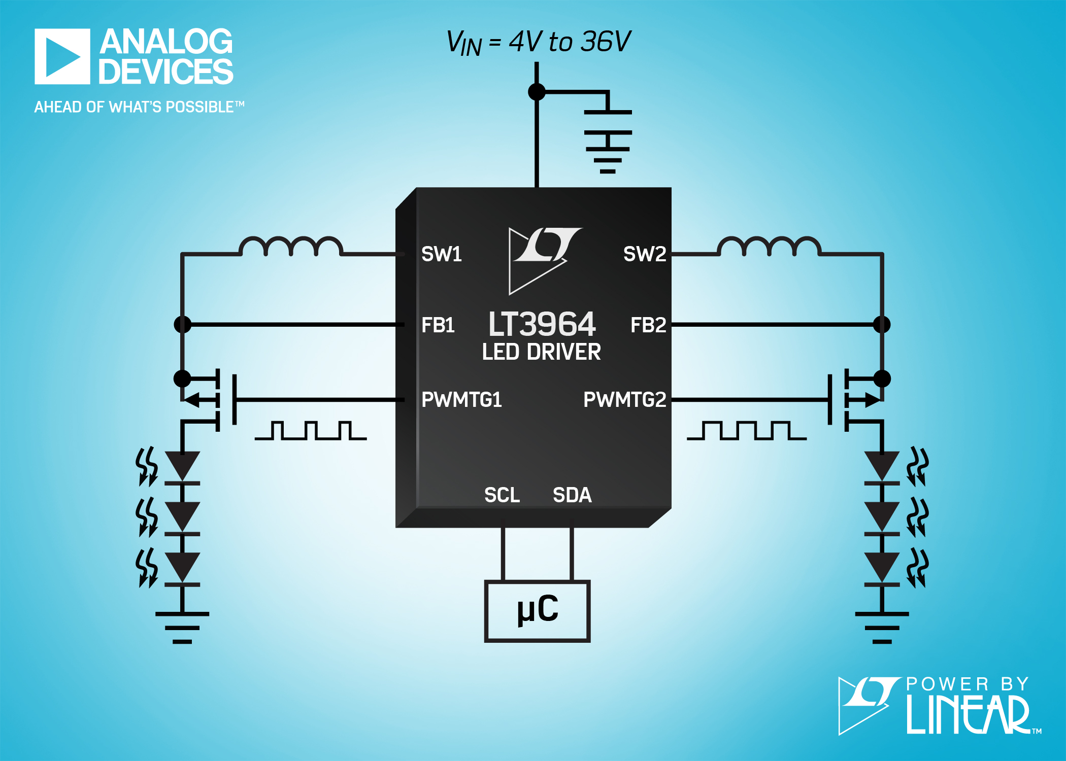
Analog Devices announces the Power by Linear LT3964, a dual channel, 36V, high efficiency, synchronous, step-down LED driver with internal 40V, 1.6A power switches and an I2C interface that simplifies LED dimming control. The LT3964 operates with a wide 4V to 36V input range, and features two independently controlled LED drivers that switch at up to 2MHz, resulting in a highly integrated, compact solution with small external components.

The LT3964 employs fixed frequency, current mode control and operates as a constant-current and constant-voltage source with accurate current regulation to provide optimal LED lighting in automotive, industrial and architectural lighting applications. Synchronous operation results in efficiencies above 94% with both channels at full current load.

Its 400kHz I2C interface greatly simplifies digital PWM dimming. A PWM signal from a microcontroller to the LED driver is not necessary; instead, internal registers are programmed with the desired dimming duty cycle, which is synchronized to the internal clock. This provides dimming ratios up to 8192:1 and eliminates beat frequencies caused when the PWM signal and the internal oscillator are not synchronized. Alternatively, with analog dimming, an I2C settable 8-bit scale factor sets the control voltage-to-LED current ratio allowing more control of analog dimming adjustments. 1000:1 external PWM dimming and 10:1 analog dimming are also provided.

The LT3964’s switching frequency is programmable from 200kHz to 2MHz or it can be synchronized to an external clock signal. LED driver protection features include open-LED and short-circuit LED fault detection, and LED overcurrent and overvoltage detection, all of which can be reported via the I2C interface. Thermal shutdown provides an added layer of protection.

The LT3964EUHE is available in a thermally enhanced 36-lead 5mm x 6mm QFN package. Three temperature grades are available, with operation from –40°C to 125°C (junction) for the extended and industrial grades, and a high-temperature grade of –40°C to 150°C.

Filed Under: LED Lighting, Power Components, Semiconductor Tagged With: analogdevicesinc, lineartechnologyinc

Reader Interactions

Leave a Reply

Your email address will not be published. Required fields are marked *

This site uses Akismet to reduce spam. Learn how your comment data is processed.

Primary Sidebar

CURRENT DIGITAL ISSUE

A frequency you can count on There are few constants in life, but what few there are might include death, taxes, and a U.S. grid frequency that doesn’t vary by more than ±0.5 Hz. However, the certainty of the grid frequency is coming into question, thanks to the rising percentage of renewable energy sources that…

More from the digital archive

DesignFast

Component Selection Made Simple.

Try it Today
design fast globle

Subscribe to our Newsletter

The Power Electronic eNewsletter delivers breaking electronic and power component news, resources, product innovations and more.

Subscribe today

EE TRAINING CENTER CLASSROOMS

EE Classrooms

RSS Current EDABoard.com discussions

  • How to set USB port as RS-485 entrance? How to interpret Growatt solar inverter commands?
  • Find Critical Path in Cadence Genus?
  • Simulation of a Press-ON-Press-OFF push button
  • HFSS 2022 R2 - Waveguide port configuration
  • Why this antenna azimuth and elevation direction are the same?

RSS Current Electro-Tech-Online.com Discussions

  • How know if solder iron has good quality tip?
  • How does a transistor works as a switch?
  • Peltier control
  • How to set USB port as RS-485 entrance? How to interpret Growatt solar inverter commands?
  • Component Identification

Footer

EE World Online Network

  • DesignFast
  • EE World Online
  • EDA Board Forums
  • Electro Tech Online Forums
  • Connector Tips
  • Microcontroller Tips
  • Analog IC Tips
  • Sensor Tips
  • Test and Measurement Tips
  • Wire and Cable Tips
  • 5G Technology World

Power Electronic Tips

  • Subscribe to our newsletter
  • Advertise with us
  • Contact us
  • About us
Follow us on TwitterAdd us on FacebookFollow us on YouTube Follow us on Instagram

Copyright © 2022 · WTWH Media LLC and its licensors. All rights reserved.
The material on this site may not be reproduced, distributed, transmitted, cached or otherwise used, except with the prior written permission of WTWH Media.

Privacy Policy