
The high-speed all-electric railroad locomotive uses a catenary-wire system and pantograph power-transfer arrangement, which appears to violate good engineering practice and should not work. Still, it does, transferring hundreds of amps via a contact point moving at over 100 miles/hour.
Part 2 of this article looked at power issues and numbers related to the electric locomotive. This part looks at the pantograph and catenary power system.
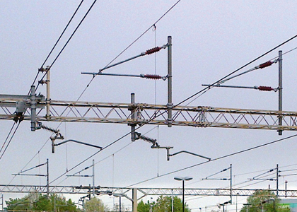
The concept of the catenary feed used on railway lines (Figure 1), was developed in the late 1800s. In theory, it’s straightforward. A wire is strung between poles and naturally takes on the classic catenary shape defined by the hyperbolic-cosine trigonometric function (see Reference). This equation was derived in 1691 by Gottfried Leibniz, Christiaan Huygens, and Johann Bernoulli in response to a challenge by Jakob Bernoulli. This catenary wire (also called a messenger wire) has closely spaced “drops,” which support the actual contact, current-carrying wire. The return path for the current is the track rail, which is at ground potential and thus not electrically dangerous.

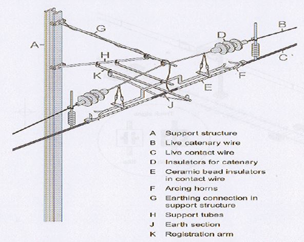
Due to the high voltages and the need to ground the metal support poles and arms, a catenary system uses many large insulators to keep the high voltage physically and electrically isolated (Figure 2) and (Figure 3).
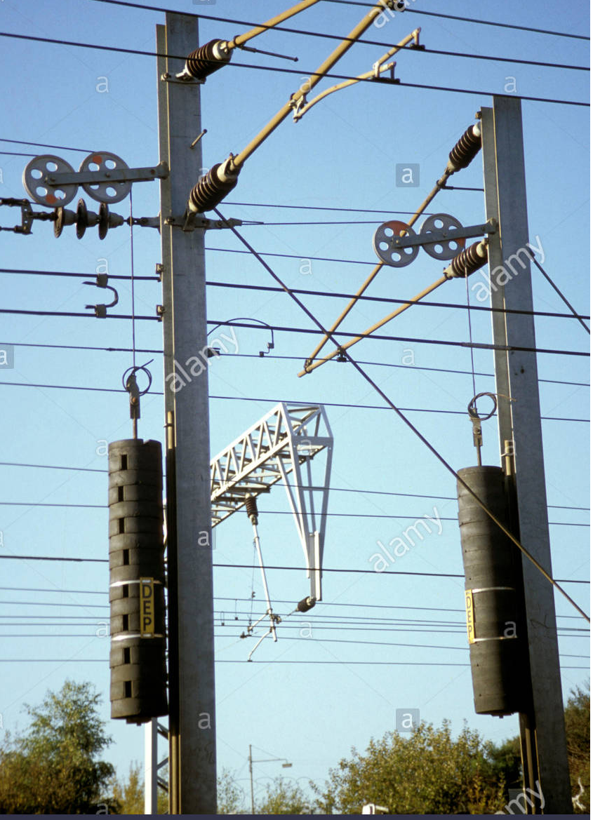
Further, the catenary wire must remain properly taut and tensioned. Some systems use hydraulic tensioners to provide tension on the catenary wire and thus maintain its shape despite changes in temperature. However, many catenary systems instead use pulleys and suspended deadweights of five to ten thousand pounds (about 2500 to 5000 kg) at the support poles (Figure 4), since this solution is simple and reliable, and the tension provided by weights is independent of temperature, unlike the operation with the hydraulic solution. By adding or removing weights, the required tension value is easily set or changed as needed for different lengths of catenary run and other factors.
(Note that there are some catenary systems, primarily in tight urban areas, which use closer pole spacings and higher tension on the catenary wire, so it very closely approximates a straight line. This eliminates the need for drops and the separate contact wire.)
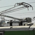
This catenary/contact wire arrangement provides supply access, but how does that power reach the load of the locomotive or individual coaches? To pick off the power, the top-mounted pantograph assembly is topped with a cross-wire contact made of special graphite-based material and reaches up from the engine or coach towards the contact wire (Figure 5). While it is at a fixed height above the tracks, the catenary wire itself does not run exactly in line to the tracks below; instead it “zig-zags” left to right and back slightly so the power pickup with wear evenly and not develop a groove from sliding at only one point. It then pulls the current from the overhead supply as it travels underneath it.
The pantograph can be remotely raised or lowered as needed; most locomotives have two, with the rear one being used first and the front one as a backup. The pantograph assembly uses springs to maintain just the right amount of tension of the graphite block against the catenary wire even at full speed despite the spacing varying slightly between the locomotive and wire due to irregularities in the rail or wire placement. This pressure is critical: too low a contact force leads to the formation of arc while too high a force causes excessive and rapid wear at pantograph contact strip and catenary wire.

Some urban “trackless trolleys” or electric busses also use an overhead wire for power in a technique somewhat similar to an electrified locomotive. However, there is no ground-level current-return path due to the rubber tires and the absence of ground-level tracks. To provide the return path, these vehicles use dual, parallel overhead wires and a pair of overhead poles for pickup and current. These dual poles act as simplified pantographs for current pickup and return and are free move somewhat independent of each other to accommodate the realities of turns and other street-related situations.
Part 4 will look at one class of potential problem that this high-voltage operation and arrangement can bring, and now to detect it.
EE World References
“Electrified Locomotives, Tunnels, and the Pennsylvania Railroad: Astonishing engineering but a partially sad ending, Part 1: The challenge”
“Electrified Locomotives, Tunnels, and the Pennsylvania Railroad, Part 2: The tunnels”
“Electrified Locomotives, Tunnels, and the Pennsylvania Railroad, Part 3: The station”
IGBT 1,200V/900-A-rated modules handle industrial drives, heavy-duty vehicles, power inverter apps
Gate-driver system targets new 1.7-kV to 4.5-kV IGBT/SiC dual power modules
IGBT module platform handles 450-A at up to 6.5 kV
Magnetic gear tooth sensor IC optimized for traction motor apps
Wide-input-range, high power density dc-dc converters optimized for railway traction, rolling stock apps
DC-DC Converters for Railway Traction and Rolling Stock Applications
External References
- Engineering Toolbox, “Cable Loads”
- The Railway Technical Website
- Ofil Systems, DayCor Rail
- Engineering Master, “Working of electric locomotive”
- Engineering Master, “What is Pantograph?”
- Allied Insulators, “Transmission & Distribution”
- “Railway Signalling Concepts”
- net, “Electric Traction Systems”
- Wikipedia, “Third Rail”
- Pennsylvania Railroad GG-1 Electric Locomotive
- Curbside Classic, “Trackside Classic: Pennsylvania RR GG1 #4935

Leave a Reply