
Trends including the emergence of 5G telephony and the continued expansion of the Internet of things (IoT) are causing the density of electronic devices to increase dramatically. That increases the density of potential sources of electromagnetic interference (EMI) and the dangers associated with a lack of electromagnetic compatibility (EMC). The result is likely to be a continued expansion and tightening of EMI/EMC standards. This FAQ briefly considers today’s EMI/EMC regulations landscape, then reviews various passive approaches to controlling EMI and mitigating its impact; it closes by looking at active EMI mitigation techniques.
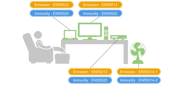
Even today, there’s an extensive number of EMI/EMC standards that designers must consider (Figure 1). For example, just considering EMC testing, Wikipedia lists 94 standards; 15 CISPR (Comité International Spécial des Perturbations Radio) standards, 21 IEC (International Electrotechnical Committee) standards, 14 ISO (International Organization for Standardization) standards, 19 SAE (Society of Automotive Engineers) standards, 20 combined EN (European Norms) and VDE (Verband Deutscher Elektrotechniker) standards, and 5 combined FCC and MIL standards in the U.S.
Basics of EMI filtering
All modern digital electronics, including switching power converters, require some level of EMI filtering and EMC control. EMI filtering can be simple using individual capacitors or inductors for targeted and limited EMI filtering needs. In some instances, much more complex filter networks are required.
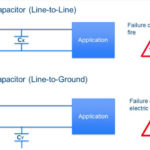
Capacitors can be used inline or as a shunt to ground. An inline capacitor will attenuate DC and low-frequency AC signals while passing higher frequency signals. A shunt capacitor allows DC and very low-frequency AC signals to pass down the signal or power line while sending higher frequency EMI to ground. Factors that determine the performance of filter capacitors include the capacitance value, how and where the capacitor is connected in the circuit, and the performance variations of the device under varying environmental conditions and various power levels.
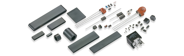
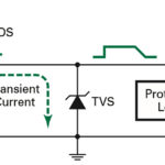
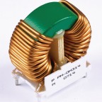
EMI suppression filter components take a variety of forms and employ numerous technologies (Figure 2). Inductors or transformers can also be useful for both common-mode and differential-mode EMI filtering. When inductors, also called chokes, are in line with power lines, they absorb a significant amount of EMI beyond 50/60 Hz up to a few hundred Hz and don’t impede power transfer. Like capacitors, EMI chokes can be placed directly onto a PCB between the downstream circuitry and the power lines. But there are many instances where individual capacitors or chokes do not provide the needed level of filtering. That’s where EMI filter assemblies come in.
EMI filters
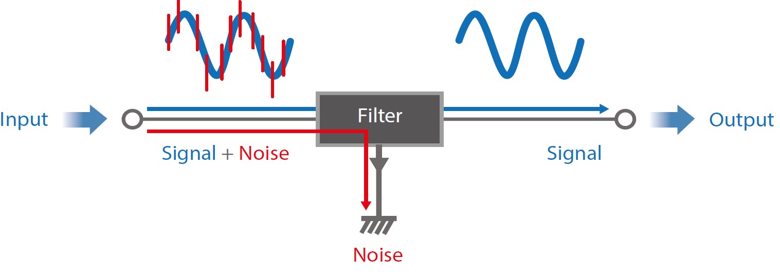
EMI suppression filters reduce common-mode and differential-mode EMI and can even improve device immunity (Figure 3). These filters are specially designed frequency-dependent attenuators. Standard EMI filters are available that can be inserted between AC power lines, DC power lines, and signal lines to filter unwanted noise from tens of kHz to tens of MHz. EMI/EMC concerns are often unique to a specific product design and may require a custom solution.
The wide variety of equipment and an equally wide variety of EMI/EMC standards necessitates the development of numerous filtering solutions. Depending on the specific application’s needs, designers can select from varying degrees of filter complexity, including single-stage, two-stage, and multi-stage units. Additional stages can attenuate specific frequency bands or provide greater attenuation over a wider spectrum of frequencies. EMI filters are also available in a variety of package formats, including:
PCB filters can provide a compact and cost-efficient EMI filtering solution that can be mounted on a PCB with standard through-hole soldering. PCB filters can be single-stage or multi-stage designs. Multi-stage PCB filters can provide high conducted EMI attenuation in a small footprint for applications that require greater EMI filtering in a restricted space.
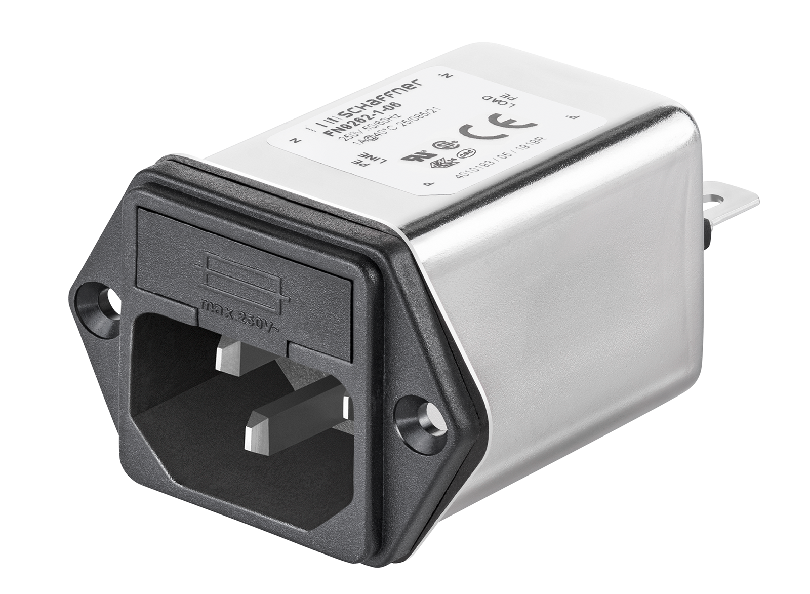
IEC inlet filters are single-phase filters built into standard IEC inlets or power entry modules rated 250 VAC (Figure 4). These filters can be useful with portable electrical equipment, household devices, medical systems, test and measurement equipment, and rack-mount equipment that requires high conducted attenuation between 10 kHz and 30 MHz.
Single-phase EMI filters are designed for installation in AC or DC lines with a positive and negative, or dual, signal/power path. Like IEC inlet filters, this type of filter heavily attenuates signals from 10 kHz to 30 MHz. General purpose, single-phase filters can be useful in AC/DC power supplies, small motor drives, office equipment, and other systems that are powered from single-phase AC. Some designs are optimized for specific performance requirements, such as in medical or industrial equipment.
Three-phase EMI filters are designed for use in higher power motor drives and power conversion applications. Some three-phase filters include filtering on the neutral line. These filters are often used as AC input filters for automation systems, machinery, and general industrial equipment. Some designs have low leakage and can be used in medical equipment.
DC filters are optimized for use on DC power and control signal lines. They are similar to AC filters but are optimized for DC signals and have higher DC voltage and current ratings. DC filters are often used with solar panels, various types of battery chargers, DC motor drives, and inverter/converter systems. For example, when used with solar panels, DC filters can prevent premature aging caused by conducted emissions and leakage currents.
Feedthrough filters are an example of application-specific EMI filters. They are inline filters designed to provide attenuation up to 1 GHz and higher. These filters provide higher attenuation than feedthrough capacitors, especially when source impedances are below 50 Ohms. Feedthrough filters are used to protect sensitive equipment within shielded enclosures such as high-performance computing and communications systems.
Active EMI mitigation
When passive EMI filters don’t provide the needed performance, designers can turn to active EMI mitigation. The two most often used active EMI mitigation techniques are spread spectrum clocking (SSC) and active filtering. SSC is used to reduce the EMI generated by a system, while active filtering provides enhanced EMI filtering.
SSC modulates the clock frequency slightly to lower the peak energy generated. SSC reduces total EMI at both the fundamental frequency and its harmonics. Two common SSC implementations are center spreading and down spreading. As the name implies, center spreading modulates the clock frequency evenly around the nominal frequency. Down spreading modulates the frequency below the nominal frequency. In power conversion applications, center spreading of most often employed. Some digital chips such as CPUs may have a maximum clock frequency specification and require down spreading.
Active EMI filtering (AEF) is implemented in a three-stage process: First, the EMI is sensed and measured using either capacitive sensing to sense voltages or a current transformer to sense currents. The sensed signal duplicates the frequency, magnitude, and phase of the EMI; The inversion stage produces an amplified and inverted copy of the sensed EMI signature; Finally, the inverted copy of the EMI is injected back into the system with opposite phase to reduce or cancel the EMI.
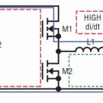
For example, power converter controller ICs are available that include built-in AEF capability (Figure 5). In this design, the differential mode conducted emissions are reduced at the input of the converter. The AEF section of the buck controller senses the EMI then amplifies and inverts the signal before injecting the corrective signal through the inject capacitor.
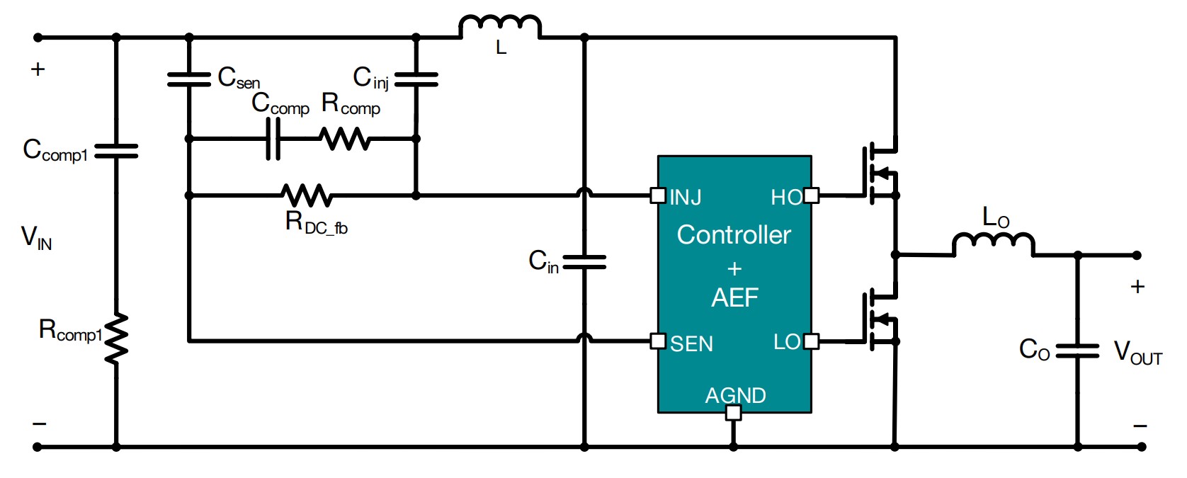
The use of AEF minimizes EMI generation, reducing the need for EMI filtering, which enables the use of smaller and lower-cost filter components. AEF does not impact the normal operation of the dc/dc converter since it is designed to act only on the high-frequency noise and is transparent to nominal operation.
Summary
The importance of EMI filtering and EMC designs is expected to continue to grow and result in a continued expansion and tightening of EMI/EMC standards. EMI filtering is a broad field. It can be as simple as using individual capacitors or inductors for targeted and limited EMI filtering needs. In some instances, filter networks ranging from simple single-stage filters to multi-stage filter designs are needed. And when passive techniques and multi-stage filtering provide insufficient performance, designers can turn to active EMI filtering technologies.
References
Active EMI reduction, Wikipedia
Electromagnetic Compatibility Considerations for Switching Power Supplies, CUI, Inc.
EMC/EMI mitigation solutions, Schaffner Impulse
EMI Suppression Filters (EMC and Noise Suppression), Murata
List of common EMC test standards, Wikipedia
Time-Saving and Cost-Effective Innovations for EMI Reduction in Power Supplies, Texas Instruments
Leave a Reply