
Ceramics comprise the most widely used non-polarized dielectrics. The reason is they offer attractive combinations of volumetric efficiency, manufacturability, and cost. Some applications – such as high-frequency RF signal chains and high-precision measurement circuits – take advantage of the parametric performance available from other dielectrics, but currently available ceramic formulations perform well in a wide range of power interface, signal coupling, filtering, and timing circuits.
 Ceramic capacitors provide a coded nameplate designation that identifies not just capacitance and maximum working voltage. In addition, it specifies capacitor thermal behavior in conformance to EIA (Electronic Industries Alliance) standard 198. The standard divides capacitor thermal performance into three classes.
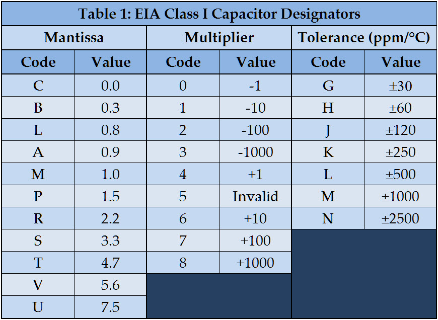
Class I devices are characterized by their tempcos (temperature coefficients of capacitance), which range in seven designations from ±30 ppm/°C to ±2,500 ppm/°C. Ceramic formulations with such low variation over temperature tend to exhibit low dielectric constants and, therefore, do not provide nearly the volumetric efficiency of ceramics for Class II capacitors. Their temperature stability makes them attractive for filtering and timing applications but such precision isn’t necessary for power-supply bypassing where lower cost per unit capacitance and greater volumetric efficiency makes Class II dielectrics more practical.
Class II devices cover a large range of thermal behaviors. Designers should consider the full range of use-cases for their products before selecting the characteristics for bypassing applications. For example, some OEMs have used capacitors with Z ratings (+10°C low-temperature limit) for decades in consumer, small office/home office, and some light-duty commercial products. But the trend away from stationary product installations means that a system’s operating environment is far less predictable than it once was. And with the growing IoT sector, there’s a higher probability of blowing past Z-rated capacitors’ lower operating-temperature limit.
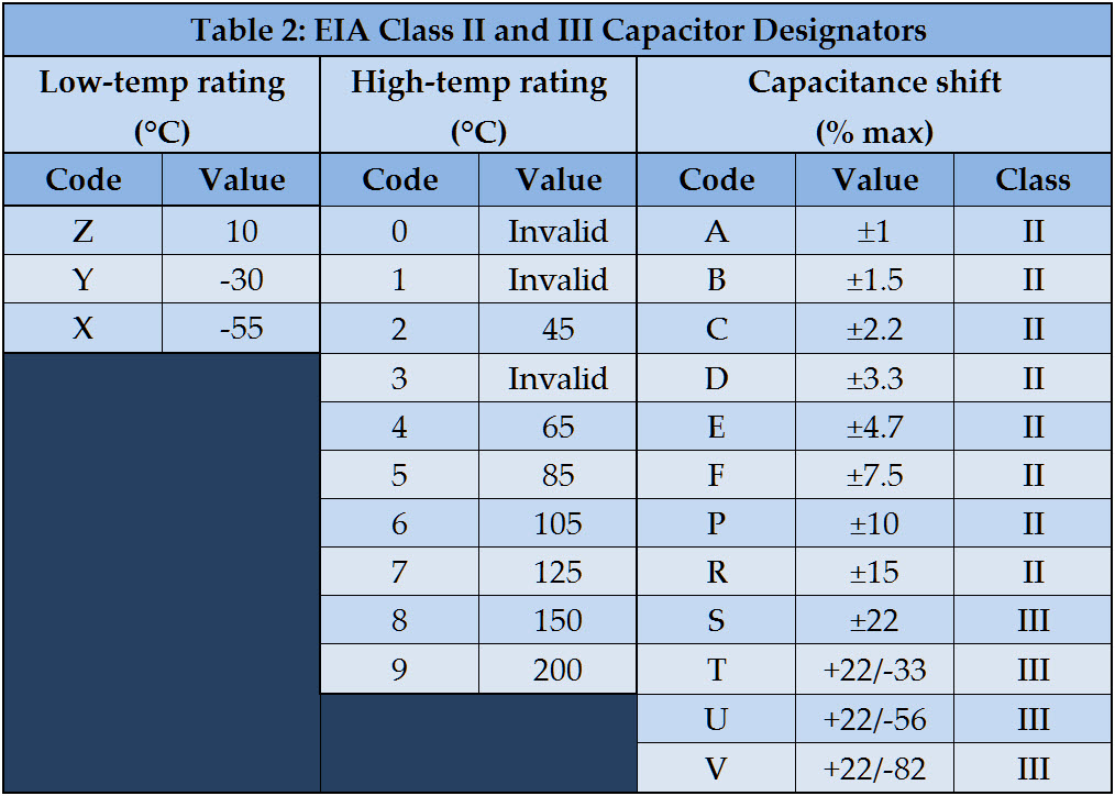 Similarly, bypass capacitors for consumer applications often have exhibited large swings in capacitance over their operating temperature range. Z5U dielectrics, for example, can lose more than half their room-temperature capacitance over their comparatively narrow operating temperature range. As we push functional electronics harder and harder, providing rock-solid power rails becomes ever more important. Skimping on bypass capacitors may save a few pennies but can risk product performance in ways that are difficult to diagnose.
Temperature isn’t the only operating condition that affects the capacitance of ceramic devices. Applied voltage does as well. Alas, ceramic capacitors’ nameplates do not have a designation that describes the relationship between the two. Complicating matters, specific designations such as X7R do not identify specific dielectric formulations. Any ceramic that delivers the same or better capacitance vs temperature behavior specified by the X7R designation can be labeled as such.
Different formulations that meet those criteria will exhibit different voltcos (voltage coefficients of capacitance). To know what you’re getting, you need to refer to the capacitor data sheet.
As a general rule of thumb, a device with larger footprint will exhibit a smaller voltco than one with a smaller form factor. Also as a general rule of thumb, capacitors with higher maximum working-voltage ratings have lower voltcos than lower-voltage devices. But each capacitor manufacturer’s dielectric formulations are potentially unique to that vendor. Specifying, say, a 4.7-µF 10-V X7R cap with an 0805 footprint isn’t sufficient. Were you to measure samples from five different component manufacturers you might observe five different voltco behaviors. At a minimum, you need to check the manufacturers’ datasheets and also check your company’s AVL (approved vendor list) for each ceramic cap part number.
Finally, the capacitance of ceramic caps changes as a function of frequency. The data sheet’s spec table usually gives the nameplate capacitance at one frequency — often 1 kHz. With modern switching power stages operating in excess of 1 MHz, you’ll want to familiarize yourself with how your bypass capacitors perform in the spectrum of interest. The general trend is negative with increasing frequency and can be more than -10% at your supply’s switching frequency.
More info: Tips on applying electrolytic capacitors
Leave a Reply