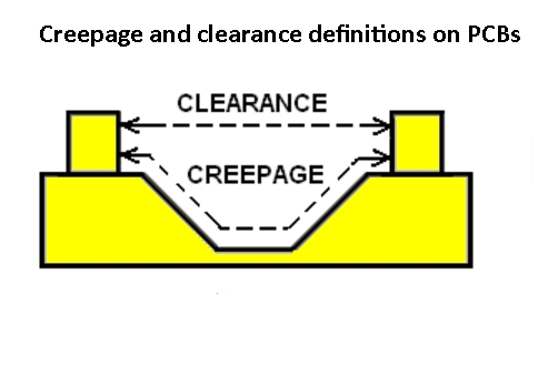
Electronic circuits accomplish so much with single-digit supply voltages that it’s easy to lose track of the precautions that higher-voltage circuits demand. But getting to those single-digit supplies often requires power-train sections operating at hazardous potentials. Although human safety is a key concern, it isn’t the only one. If sufficient clearances aren’t maintained between conductive surfaces, voltages sufficiently high to ionize the air between result in arcing events that are most often destructive and, at best, compromise equipment robustness and reliability.
Although potentials generally run downhill from power entry to point of load, they often don’t do so monotonically. For example, PFC (power-factor correction) blocks often present outputs that operate in the neighborhood of 400 V —- substantially higher than their mains power-entry voltages. Even some battery-powered applications generate high potentials. The flash circuits in portable so-called speedlite strobes for digital cameras typically operate at around 300 V, derived most often from either a small Li-ion pack or from a few NiMH batteries and one heck of a boost converter.

In many industrial applications, sensor nodes require galvanic isolation from the control system tested to 1.5 kV. Although most circuits on either side of the isolation barrier operate on common single-digit supplies, the barrier itself must include sufficient spacings to prevent flashover due to the high common-mode voltages applications can impose on these nodes.
As opposed to voltage-related failure mechanisms that can result from incremental degradation over long periods, flashovers are initiated by instantaneous conditions – the peak transient applied voltage key among them. Unlike momentary voltage excursions, however, other contributors to the instantaneous conditions tend toward less dynamic behaviors and modulate over longer intervals and are, therefore, easier to neglect in the context of transient events.
For example, the ionization of air is a function of not just instantaneous voltage, but also temperature, relative humidity, altitude, and concentration and type of pollutants. So your design and design-evaluation criteria must anticipate these real-world environmental variables. Certain aspects of your design, not otherwise associated with clearance considerations, can also play a role in a product’s field performance. For example, forced-air fans -— part of the thermo-mechanical design quite divorced from circuit operating conditions -— can draw in humidity and pollutants to a far greater degree than would be the case with passively-cooled or liquid-cooled designs without air blowers.
Standards tend to promulgate along two primary axes: by geopolitical region according to regulating body or other standards authority, and by application. Major originators of standards have, in recent decades, recognized the need for equipment manufacturers to supply a global marketplace and have put significant effort into harmonizing standards when practical.
Standards, therefore, increasingly tend to be differentiated primarily by application. Many standards organizations have tried to group applications to the extent that’s practical, but the effort can be limited. For example, patient-connected medical equipment and laboratory gear may share a great deal in common with regard to their operating temperature, humidity, altitude, and types and concentrations of pollutants. In some ways, medical equipment may enjoy a more benign set of operating conditions. Nonetheless, medical applications most always demand more stringent standards if for no other reason than that the consequences of failure are more dire than for, say, a rack of ATE gear.

One approach to codifying pollutant type and concentration is based on simple, qualitative descriptions of the operating environment because referencing specific pollutants and concentrations drives up the cost of compliance without adding a corresponding degree of benefit. For example, UL 61010 – Safety Requirements for Electrical Equipment for Measurement, Control, and Laboratory Use (harmonized with IEC EN 61010) – identifies four baseline operating environments and stipulates spacing requirements for each. So determining spacing minimums isn’t as simple as plugging a voltage level into an equation or looking it up in a single, universally applicable table.


Leave a Reply