
Among the many available topologies used for power-supply converters, the flyback design offers some distinct advantages along with unique idiosyncrasies.
There’s a wide and diverse array of power-supply converter topologies among which to choose, each with tradeoffs in their various performance attributes and cost. The flyback design is a converter approach that has been used for 70+ years and is still in use, now using an IC as a controller and various approaches to physical implementation.
Q: What is the role of a power converter?
A: In principle, it’s simple: take a power source (sometimes regulated, sometimes not) and transform it into a regulated output voltage at up to a specific current level, or deliver a regulated current with a required compliance voltage.
Q: What are some of the performance parameters?
A: There are many. Of course, cost is almost always among them, but technical issues are regulation, accuracy, transient performance, ripple and filtering, EMI generation, efficiency at specific load points and across a load range, size, weight, BOM complexity, stability, temperature performance, and performance despite component tolerances. Other factors include isolated versus non-isolated design, which is defined by the application.
Q: What is the flyback converter?
A: A flyback converter is a simple implementation of a switch-mode power supply (SMPS), and it can be designed to deliver a DC output from either an AC or DC input, with outputs both lower and higher than the supply source (buck/boost operation). It has two distinct operating phases, with a basic principle that power from the input side is transferred to the output side only when the primary-side switch is off and its current flow is zero or close to it.
Q: Where and why is the flyback approach used?
A: It is generally used in what is considered the low-to-medium power range, around 100 to 250 W or less. The basic flyback design has a fairly short and low-cost BOM: input capacitor, primary-side MOSFET switch, output (secondary)-side rectifier diode, and an output capacitor. In addition, there is the flyback transformer itself.
Q: What are some good-fit applications for the flyback design?
A: It is widespread in use, for both higher and lower output voltages. Many multiple-output PC supplies use it to generate the needed rails at various lower voltages. But it is also used for power-over-Ethernet (PoE), and for developing much-higher voltages such as the ~20 kV needed by now-obsolete CRTs, and high-intensity xenon flash tubes.
Q: Is the flyback design new?
A: Not at all. It was developed in the 1930s and 1940s and highly refined in the 1950s with the introduction of commercial television. In that role, it was needed for the high CRT voltage, as noted, and the other voltages for the vacuum tubes. As a result of this vast market, the flyback converter was engineered and optimized for low cost, high reliability, safety, and manufacturability.
Q: What’s special about the flyback transformer?
A: Unlike a conventional transformer, which is used only to step a voltage up or down, the flyback transformer is also used as a magnetic energy-storage element (thus functioning as an inductor). It is not just a basic two-winding (primary/secondary) transformer but has additional windings that are essential to the flyback operation. The transformer turns ratio determines the output versus input voltage, and also provides galvanic (ohmic) isolation. Further, the flyback design can support multiple outputs by using additional windings.
Q: What is the basic operational principle of the flyback approach?
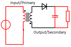
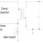
A: In concept, it is elegant and simple. When the primary-side switch is closed (Figure 1), the result is an increase in the primary current and magnetic flux in the transformer/inductor as the primary-side circuit is supplied by the source. The voltage in the secondary-side winding is negative due to the relative relationship between primary and secondary windings, so the diode is reverse-biased and blocks current flow. The secondary-side capacitor supplies the current to the load during this period.
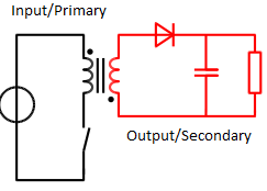
Next, the switch is opened (Figure 2), so the primary-side current goes to zero, and the magnetic flux collapses. Now the secondary-side voltage goes positive, the diode is forward biased, and current flows from the transformer secondary side to the capacitor, thus replenishing the capacitor.
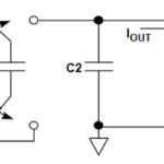
One analogy used for flyback design is that the output capacitor is like a bucket that is either being filled (recharged) or emptied (supplying the load) but never doing both at the same time. Of course, this means that the output side has ripple, which must be filtered by the capacitor, which is never allowed to drain down to zero charge.
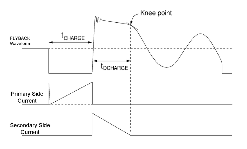
Q: So, why is it called a flyback design?
A: The sudden stop/stop, on/off action of the MOSFET switch yields a waveform that looks like a sudden reversal of current flow (Figure 3).
Q: How is the output regulated in the flyback design to maintain the desired voltage at the load?
A: This is where things begin to get complicated. It is usually done by adjusting the on/off duty cycle of the primary-side switch. In some designs, the frequency of the switching action can also be adjusted, as faster switching yields closer tracking of the output to the desired output value.
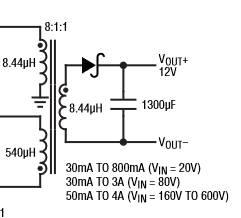
Q: How does the controller obtain the feedback it needs to determine what to do in this closed-loop situation?
A: There are two possibilities. A special winding on the transformer can be used; this is the traditional way of doing it (Figure 4). An alternative is to use an optocoupler (Figure 5), which provides feedback and maintains input-output isolation just like the transformer does.
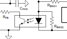
Q: Which technique is preferable?
A: As always, it depends. On one side, the transformer is usually a custom or less common unit, although there are many off-the-shelf ones designed specifically for flyback designs; still, these are not as common as regular two-winding units. On the other hand, the optocoupler requires additional support components (higher cost, more-complicated BOM, more PCB space), and there are some who feel the long-term reliability of optocoupler is not as high as desired (due to LED aging) although there have been improvements in this area.
Part 2 of the FAQ will look at the issues which affect flyback performance and what can be done to improve it, as well as IC controllers, which make the design and implementation of a flyback converter much easier.
EE World Online References
Optocouplers, Part 1: Principles and usefulness
Optocouplers, Part 2: Parameters and applications
Power-supply noise, Part 1
Power-Supply noise, Part 2
Working with higher voltages, Part 1: Voltage boosters
Working with higher voltages, Part 2: Voltage multiplier
Other References
Electrical Engineering Stack Exchange, “How does a CRT television flyback really operate”
Autodesk Instructables, “2n3055 Flyback Transformer Driver for Beginners”
Robert Gawron, “High voltage supply (10-30kV) made from CRT television flyback transformer”
Electronic Repair Guide, “What Is Flyback Transformer?
Texas Instruments, “Understanding the Basics of a Flyback Converter”
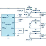
Analog Devices, “1000 V Output, No-Opto, Isolated Flyback Converter”
Maxim Integrated, Application Note 1166, “Flyback Transformer Design for MAX1856 SLIC Power Supplies”

[…] the subtle issues which degrade and impede their performance – is the real challenge. In Part 1, we looked at the flyback design and some distinct advantages along with unique idiosyncrasies. […]