
Power-over-Ethernet (PoE) and USB power delivery (PD) systems are quite different in terms of the required power controllers. Still, they are very similar in terms of output power requirements. While PoE typically uses 48 Vdc input power for local power converters, USB PD power adapters typically operate from AC mains voltages. However various PoE and USB PD implementations are typically limited to a maximum of 100W. The 100W maximum power requirements make flyback and forward converters suitable for both PoE and USB PD power systems.
This FAQ will review the cost, efficiency, and other performance tradeoffs for PoE and USB PD implemented with flyback, forward, and active-clamp forward topologies, emphasizing key power transformer characteristics and specifications.
In a PoE application, the typical input voltage for the power converter will be a nominal 48 Vdc from the Ethernet cable, and the converter will be a dc/dc topology. On the other hand, USB PD is typically an ac/dc power supply with an input range of 85 to 265 Vac. Flyback and forward topologies are versatile and can implement either a dc/dc converter or an ac/dc power supply.
At first glance, a flyback converter and a forward converter look similar. Both are typically single-switch topologies, but they operate in fundamentally different ways. It’s the magnetics that makes a big difference. The transformer in a flyback converter can be modeled as two inductors with windings of opposite polarities sharing a single core. When the switch is “ON” energy is stored in the magnetic field in the air gap. When the switch turns “OFF,” the stored magnetic field collapses, and the energy is transferred to the output. The transformer in a forward converter is modeled as a true transformer with same-polarity windings; there is no air gap to store energy, and energy is transferred directly to the output when the switch is “ON.”
Flyback topology
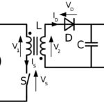
Flyback converters can provide a low-cost solution for low-current and low-voltage output power supplies (Figure 1). They provide good input-to-output isolation and do not need an output inductor. However, they have a higher output ripple current and need a larger and more expensive output capacitor. They have higher peak and RMS currents than a forward converter, which reduces efficiency.

When the main switch is ON, the transformer’s primary is directly connected to the input voltage source. The transformer’s primary current and magnetic flux increase, storing energy in the transformer. The induced voltage in the secondary winding is negative, so the diode is reverse-biased blocking current flow, and the output capacitor supplies energy to the output load. When the main switch is OFF, the primary current stops flowing, and the magnetic flux drops. The transformer secondary voltage is positive, forward biasing the diode, and current flows from the transformer, recharging the capacitor and powering the load.
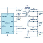
Standard flyback transformers are available for PoE and USB PD applications. For example, flyback PoE transformers can support 1500 Vac isolation from the input to output. Standard power levels include 4 W, 7 W, and 13 W, and the transformers accept input voltage ranging from 29.5 to 60 Vdc (Figure 2).
When considering a flyback transformer for either PoE or USB PD, designers should select a transformer with a peak primary current or a primary saturation current that is well above the expected primary current peak for the application. The peak current requirement occurs at the worst-case condition of maximum load and minimum input voltage. If the peak current flow exceeds the transformer rating, core saturation will occur, and the primary inductance will drop, resulting in a loss of regulation.
In addition, voltage is reflected to the primary side from the secondary side when the switch is turned OFF, and the stored energy in the flyback transformer is transferring to the load. The increased voltage stress experienced by the switch can result in damage and lower reliability. A passive resistor-capacitor-diode (RCD) clamp on the primary side can help protect the switch from excessive voltages. The drain-source voltage (VDS) is clamped at a relatively high level with a passive clamp, and the switch turns ON when VDS is high. A high VDS increases turn ON losses (reducing efficiency) since switching loss is proportional to (VDS)2.
In an RCD clamp, the leakage-inductance energy absorbed by the capacitor is dissipated in the clamp resistor. This loss of energy limits the switching frequency, which results in the need for a larger transformer. A passive clamp provides low-cost protection for the main switch but increases losses and reduces switching frequency. Those limitations can be addressed with a higher-cost active clamp solution.
Active clamp flybacks
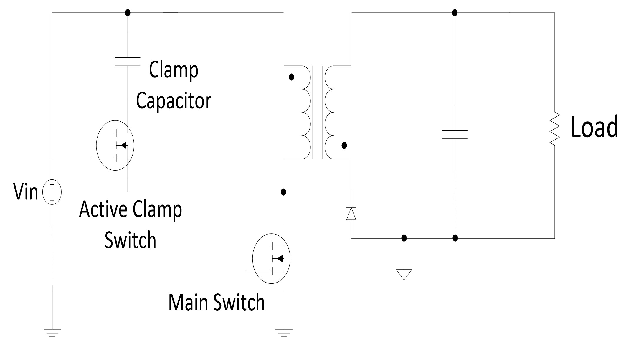
An active clamp flyback recirculates the energy instead of dissipating it, improving efficiency (Figure 3). When the main switch is OFF, the clamp switch sends the clamp capacitor energy to the secondary just before the main switch turns ON. And the clamp ensures that the main switch turns on when VDS is near zero, reducing switching losses and reducing EMI generation. The use of an active clamp can also enable a lower voltage rating synchronous FET on the output, which can reduce costs and/or lower ON resistance, further increasing efficiency.
Forward topology
Forward converters are essentially buck converters that use a forward-mode transformer. In PoE and USB PD applications, the transformer steps down the voltage and provides a safe dielectric isolation between the input and output. The main limitation of forward converters is that the maximum duty cycle is about 50 percent. The transformer in a forward converter includes a ‘reset winding’ (Figure 4). The core is driven in a unidirectional manner, and the core can saturate after a few cycles unless it is reset or ’emptied’ of excess magnetization energy. When the power switch is OFF, and the rectifiers are not conducting, the transformer is reset by drawing current from the reset winding. In most designs, the reset winding is a separate winding, but the primary winding is sometimes used to reset the transformer core. Current from the reset winding is returned to the input capacitor and reused during the next cycle of operation.
Forward-mode transformers are fundamentally different from flyback transformers. A specific magnetizing inductance and a gapped-core construction are needed in a flyback, allowing the transformer to store high levels of energy without going into saturation. A forward-mode transformer has high primary magnetizing inductance to support efficient energy transfer between the windings. Lower secondary RMS current in a forward converter than a flyback results in lower losses, contributing to higher efficiencies in forward converters. In addition, the output capacitor in a flyback must handle the higher RMS currents, increasing the capacitor losses in a flyback compared with a forward topology.
Like flyback converters, forward converters can benefit from an active clamp. In a forward converter, the active clamp is used to implement transformer reset (Figure 5) efficiently. An active clamp provides a good balance between high performance and moderate cost. Zero-voltage switching (which reduces switch voltage stress), extended duty cycle range, reduced EMI, and significant improvement in efficiency result from the use of an active clamp transformer reset.
Summary
Flyback and forward converters are suited for PoE and USB PD isolated power solutions. They are both cost-effective single-transistor solutions but offer different mixes of features and benefits. The energy storage is in the (air-gapped) transformer in a flyback converter. A forward converter uses a transformer without an air gap, requiring an additional energy storage inductor. A basic forward converter is more complex than a flyback and more efficient. In addition to the basics, designers can choose to include an active clamp for energy recirculation, further enhancing the efficiency of the designs.
References
Magnetics for Power over Ethernet (PoE), Coilcraft
Power-over-Ethernet (PoE) application notes, Eaton
Power over Ethernet PD Power Converter Transformers, Coilcraft
The One−Transistor Forward Converter, ON Semiconductor
Understanding and Designing an Active Clamp Current Mode Controlled Converter, Texas Instruments=
What is Active Clamp Flyback?, Silanna Semiconductor
Leave a Reply