
Unlike better-known electromagnetic motors, the widely used piezoelectric-based motor/actuator provides precise, repeatable linear motion over short distances, and requires a voltage drive rather than a current drive.
When we think “motor”, we usually think of rotating motion or perhaps a special “linear motor” which is a rotary motor which has been rolled out flat. To transform such rotary motion when linear motion is needed, then some sort of gearing arrangement can be added, but this brings issues of size, weight, cost, backlash, friction, and other mechanical “ailments.” Since there are applications which need small, precise, linear motion and for which a rotary (or flat rotary motor) is adequate, another approach is needed. The solution is a completely different type of solution: the piezoelectric motor/actuator. This FAQ will discuss the piezoelectric approach and the electronics needed to drive it.
Q: Wait — is this the same piezoelectric effect used in so many other situations?
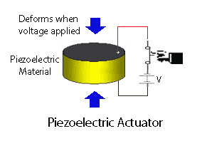
A: Yes, it’s the classic piezoelectric effect: when a crystal is “squeezed” (stressed) it generates an electric field (voltage), as well as the complementary action that when an electric field (voltage) is applied to a crystal, it changes its dimensions slightly and elongates (Figure 1). This effect is used in audio sounders/buzzers, small speakers, frequency-setting oscillators, pressure transducers, self-powered spark generators, and many other applications. A paper published in 1880 by Pierre and Jacques Curie announced the stress-to-electric charge discovery
Q: Where it is used as a motor or actuator?
A: There are many situations which need linear motion over a small range of nanometers to millimeters, and this motion needs to be precise, swift, and controllable. That’s where the piezo motor (also called an actuator) is used. These applications include medical infusion pumps, ultrasound diagnostic transducers, microscope-positioning stages, disk-drive arm assemblies, ink-jet printers, haptics systems, mirror/lens micro-positioning, to cite just a few; it’s a surprisingly long list. While a rotary motor could be used in some, but not all, of these, there would be many complications. The linear-motion piezoelectric-based actuator is a “direct drive” approach, with no gears or linkages needed.
Q: How is the piezoelectric principle applied in these cases?
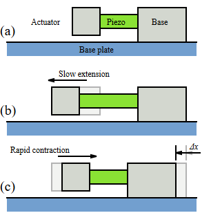
A: It can be done in one of two ways. In one approach, one end of the piezoelectric crystal element is permanently “clamped” or fixed in position (Figure 2). As a voltage is applied and removed, the crystal elongates and then returns to its original dimensions. In this way, the actuator moves back and forth from a known zero-point reference. The motion is like that of a tightly controlled piston, as the amount of elongation is highly proportional to the applied voltage.
In the other mode, often referred to as the “inchworm” mode, the piezo material is alternately be held and then released by a set of tiny piezo-based clamps, thus allowing the crystal to “inch” forward (Figure 3).

Q: What are some of the typical numbers for physical size, range of motion, and force associated with a piezo actuator?
A: The numbers span a wide range, and are a function of the crystal size, material, whether a single- or multilayer construction is used, and other factors. Note that the crystal material elongates very slightly, on the order of 0.01 to 0.1 percent. A typical crystal element is small and light (a major virtue in many cases) at about 10 mm across each dimension. Despite the diminutive dimensions and motion, a significant force can be developed — on the order of newtons. It’s somewhat analogous to liquid water turning into solid ice: the volume of the water mass expands by about 4%, but the force it develops as it does so can break pipes!
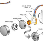
By using larger crystals or stacking multiple ones, it is possible to have motion on the order of tens of millimeters and even centimeters, with forces ranging into the tens of newtons. These actuators are available as standard devices from many vendors in sizes ranging from small to very large, multilayered units (Figure 4); custom units are also often used at modest cost.

Q: What about speed and precision?
A: Due to their small size, low mass, and the inherent physics of the situation, they can be operated at a high rate, with motion “action” reaching into the multi-kHz range — difficult to impossible with conventional electromagnetic motors — and their motion is precise, repeatable, and controllable.
As an added advantage, they are “clean” with no bearings and so need no lubrication (which may cause contamination), and their non-metallic nature is an advantage in situations and may even be a necessity, as in MRI machines.
Q: From where do these “crystals” used for the piezo actuator come? Are they natural quartz or other minerals?A: They could be, and the first discoveries and implementations were made using various “natural” crystals. Today’s piezo materials are not found but are fabricated using a variety of engineered materials which are cultivated as crystalline material with properties tailored to the desired characteristics of the final product.
Thus far, we have looked at the piezoelectric element itself, but not what drives them. That will be covered in Part 2.
References
- EEWorld, “Basics of AC, DC, and EC electric motors (Part 2) — EC and stepper”
- EEWorld, “Basics of AC, DC, and EC electric motors, Part 1— AC and DC”
- EEWorld, “Piezoelectric sounder puts out 100 dB to alert vehicle drivers”
- EEWorld, “Mechanical vibration for electronics: the quartz crystal”
- Piezo Systems, History of Piezoelectricity
- Analog Devices, ADA4700-1 data sheet
- Texas Instruments, DRV8662 data sheet
- Microchip Technology, AN2014, “Piezoelectric Micropump Driver Reference Design Application Note”
- Apex Microtechnology, PA79 data sheet
- Apex Microtechnology, AN44, Driving Piezoelectric Actuators
- ANSYS Inc, “Multilayer Piezoelectric Actuators: Can a Single Layer be Modeled to Simulate the Layered-stack?”

Leave a Reply