
 Infineon Technologies AG adds two power boards to the family of iMOTION™ Modular Application Design Kits (MADK). The two half bridge boards complement the compact and flexible evaluation system providing a scalable design platform for 3-phase motor drives in the range from 20 W to 300 W. The MADK aims at applications in the field of industrial and home appliance, e.g. pumps, fans, air conditioners and major home appliances. The new power boards additionally address battery powered applications. Using the kit, a functional motor system will be running in less than one hour, enabling fast time to market.
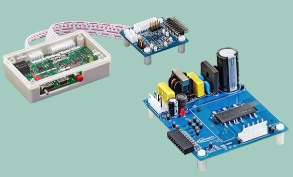
The new power boards are based on the µIPM™ from Infineon and come in power ratings of 100 V/20 A and 40 V/6 A. They feature an overcurrent/under-voltage lockout protection with fault output and an onboard power supply of 15 V and 3.3 V, respectively. Since no heat sinks are required, developers can optimize the copper area of the PCB for thermal performance. In combination with an XMC1302 or IRMCK099 control card, designers only need a few steps to run the motor: plug the cards into the PC, motor and grid equivalent voltage supply and download, install and set the parameters of the software.
The Field Oriented Control (FOC) software supports sensor-less motor control based on the XMC1302 microcontroller. The XMC1302 control card includes a debugger based on Segger J-Link technology. Additionally, the software support for this tool includes an easy to use μC-Probe based GUI. Further application software development can be implemented via DAVE™, Infineon’s free-of-charge integrated development environment (IDE), or with major ARM® IDEs, like Keil, IAR or Atollic. The IRMCK099 based control card with debug MCE-tool 2.0 features the patented and field-proven motor control engine (MCE) from former International Rectifier.
The two power boards will be available shortly at www.infineon.com/MADK and distributors worldwide. This link also leads to full software packages for each kit as well as additional information on the iMOTION MADK. Based on the CIPOS™ Mini, two additional power boards allowing for motor control of up to 2 kW will be launched in mid-2017.
Leave a Reply