
A few simple techniques can boost the efficiency of modern PoE designs.
Charlie Ice, Imre Droppa • Silicon Labs
The latest Power over Ethernet (PoE) technology delivers enough power to meet the needs of today’s WiFi6 routers, IoT gateways, and 5G small cells. PoE now delivers up to 71 W of power over standard Ethernet cables. At this power level, efficiency becomes critical to a PoE Powered Device (PD) system, which receives power via the Ethernet cable. There are several ways to improve the efficiency of the PD system and to boost the efficiency of the flyback converter commonly used to step the PoE voltage down to a usable level.
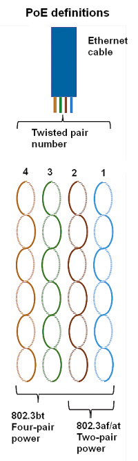
PoE transmits power over the Ethernet cable by injecting ~50 Vdc onto the twisted pairs. The dc voltage is applied through the center taps of the Ethernet transformers, and either two or all four of the four twisted pairs in the cable deliver power. The latest IEEE 802.3bt PoE standard uses the four twisted pairs.
Many papers and articles have been written describing in detail how the PoE standard works. For a PoE PD system, it is key to understand that the IEEE standard does not require that power from the Ethernet switch be injected in any specific polarity. Therefore, the PD must include rectifier bridges on the input to set the dc polarity for the system. Furthermore, most PoE PD systems do not operate from ~50 Vdc but rather operate from a lower voltage, often 5 Vdc. This practice necessitates use of a dc-dc converter to step the PoE voltage down to something usable by the system. The PoE input and the dc-dc converter combine to determine the overall efficiency of the PoE PD system.
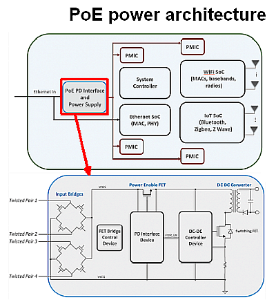
The PoE PD interface includes input bridges to set the polarity of the PoE voltage, a power-enable FET, and the PoE interface IC which is sometimes combined with the dc-dc controller into a single device. There are three fairly simple ways to improve the efficiency of a PoE PD system that do not involve the dc-dc converter, and all three ways improve the efficiency of the PoE PD interface.
The biggest improvement in efficiency comes from using FET bridges instead of diode bridges. However, it is also the most expensive improvement to implement. Most PoE PD systems use diode bridges to define the positive and negative rails. The diodes are inexpensive and provide the option of using Schottky diodes to reduce the resulting voltage drop across the diode bridges. However, the power loss adds up quickly in a 71-W system, and the extra heat complicates compact designs. Use of actively controlled FETs for the bridges reduces the power loss and thermals considerably.
Higher efficiency also results when the PoE interface IC gets power from an aux winding on the Ethernet transformer. PoE interface devices must be able to operate from the PoE input voltage. However, many of them also include the option to switch to an auxiliary supply once the dc-dc converter is running. In a flyback or forward topology, an extra winding can be added to the transformer to generate a low-voltage rail to power the PoE interface device.
For example, a device that draws 5 mA of current will dissipate 250 mW (50 Vx5 mA = 250 mW), running from the PoE input. However, if running from a 15-V auxiliary supply, it dissipates 75 mW (15 Vx5 mA = 75 mW), a significant savings. While the efficiency gain is not as dramatic as that available through FET bridges, the auxiliary input is still a simple way to reduce power consumption.
The third way to boost efficiency is via a power-enable FET with low on resistance. As the name implies, the power-enable FET enables power to the dc-dc converter once PoE negotiations have completed and power is applied to the PoE PD. All the power for the PoE PD system must flow through this FET, so reducing the FET “on” resistance is another easy way to improve efficiency. Many PoE interface devices integrate this FET on-board. If the device can drive an external FET instead, selection of an external FET with lower “on” resistance can reduce power dissipation.
PoE power supply topology
Flyback converters have served in PoE systems for years because they are efficient, inexpensive, and provide isolation. A flyback is typically used for systems needing up to 30 W of power. Beyond this level most designs employ a forward converter to step-down the PoE voltage.
A flyback converter uses a specialized transformer to both transfer power and to step down (or even up) the input voltage. Though ordinary transformers typically do not store energy, the situation in a flyback converter is different. That’s because the transformer is constructed as two coupled inductors with an air gap.
Most PoE PD device manufacturers provide evaluation boards that include a dc-dc converter along with a custom transformer design. Designers should be careful when selecting a transformer differing from that used on the evaluation board: The transformer characteristics are essential to the operation of the flyback converter. Even a slight difference can cause instability or dramatically reduce the efficiency of the converter.
Finlly, the use of a transformer allows a flyback converter to be isolated, with the a high impedance between the grounds on the primary and secondary sides. This quality allows the PoE PD device to safely provide user-accessible ports, grounded data connections (such as USB), and minimizes the chance of ground loops. As with anything safety related, always consult with the relevant safety team or agency.
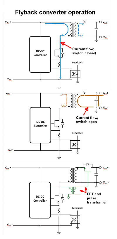
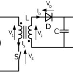
It is useful to review the role of the transformer in the flyback. When the FET is “on” (closed) current flows through the inductor on the primary side. The inductor on the secondary side does not have any current flow, as the diode connecting the secondary to the V+ output is reverse biased. Notice the polarity of the transformer creates this condition, as the opposite polarities cause the secondary side voltage to be the reverse of the primary side.
Once the current through the primary side inductor reaches a peak value, the controller opens the switch. The transformer will try to maintain its magnetic flux, and the only way to do so is to induce a current through the secondary side inductor to forward-bias the diode. The inductor current flow then charges the output capacitor and powers the load. Output voltage is primarily determined by the transformer turns ratio between the primary and secondary sides. When the switch closes, the cycle repeats with the output capacitor powering the load when the switch is closed.
There are many details to a flyback converter that impact stability and efficiency. But a simple way to improve efficiency is use a dc-dc controller with a secondary side FET driver. In this configuration, a FET replaces the secondary side diode. The controller energizes the FET when the switch is open and de-energizes it when the switch closes.
This technique improves efficiency by eliminating the voltage drop across the diode and replacing it with the voltage drop due to the FET on resistance. An additional point to note is that in an isolated flyback converter, a pulse transformer is required to transmit the gate-drive signal across the isolation barrier to the secondary side FET. Depending on the system output voltage and power level, replacing the output diode with a FET can boost the efficiency by up 5%.
Thus PoE PD efficiency can be pushed to greater than 90% from PoE-input to power-output by using a few, straightforward techniques. With up to 71 W of delivered power, PoE stands ready to power today and tomorrow’s WiFi, 5G, and IoT devices.


Leave a Reply