Whether for efficiency or due to the device physics, many applications require voltages ranging in the tens, hundreds, or even thousands of volts; the circuits which produce these voltages start with basic charge pumps and extend to voltage multipliers with simple schematics but many subtleties.
Lower-voltage circuitry is the trend, with ICs and designs operating at 5 V, 3 V, and even 1 V. There’s good reason for this: in general, such circuits require less power than higher-voltage circuits. Further, these lower-voltage circuits also can operate at higher speeds since the voltage/current swings are smaller, and so the slewing demands (dV/dt, dI/dt) are also reduced.
However, there are many cases when a higher voltage is either preferred or mandatory. This FAQ will look at techniques for a modest amount of boosting of lower voltages, as well as for increasing a voltage to a much higher value.
Q: Why would you want to use a higher voltage, since lower operating voltages offer advantages of lower power consumption and higher speeds, among other factors?
A: There are three primary reasons:
- First, a circuit may operate at a lower voltage, but need a higher voltage in some section to boost signal/noise ratio (SNR); this is common for sensitive front ends in RF and sensor applications.
- Second, when a circuit has to deliver power – not voltage – to a load, it’s always more efficient to do so at higher voltages due to reduced losses (internal, switching, IR, and I2R). In these cases, it may be beneficial, even if not mandatory, to use a somewhat higher voltage. In a typical situation, a battery and regulator providing 3 V for the main circuitry may also need to provide a 12-V rail for a sensor.
Q: Are those the only reasons?
A: Not at all. There are many real-world applications where the voltage needed is determined by the physics of the situation, and there is no way to “get around” that mandate. For example, many scientific, medical, and test systems require higher voltages (>100 V to >1000 V) to set-up specialized components such as vacuum tubes or create electric fields.
Q: OK, we need to increase the voltage at lower levels. How can we do this?
A: There are two very different ways to do this: via a transformer, or via some type of switched-capacitor arrangement.
Q: I am sort-of familiar with transformers, but how do they work?
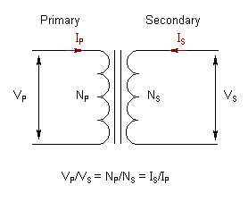
A: The transformer’s principle is simple: the AC voltage on the primary (input) side is stepped up (or down) in proportion to the turns ratio between primary side and secondary (output) side. For example, if the primary has 10 turns and the secondary has 100 turns – a 1:10 ratio – the voltage on the primary will be stepped up by a factor of ten (Figure 1). Of course, if you need a DC output, that ×10 AC output would need to be rectified and filtered. Use of a transformer to increase or decrease an AC voltage been known for about 150 years and is widely used to step up/down voltages in power-line installations, of course. However, it is often not the best choice for small circuits.
Q: This seems fairly simple (which is good), so what’s the problem?
A: While the transformer is very good at voltage step-up (or step-down) for larger systems, it is relatively large, costly, and heavy relative to a modest PC board. Further, it is not compatible with IC processes and packaging, and so would have to be mounted as a separate unit. Despite these drawbacks, it is sometimes still the right solution with respect to various tradeoffs.
Q: If a transformer is not the appropriate solution, what are some alternatives?
A: The alternative is usually a circuit which uses some arrangement of switched capacitors. These are clever schemes that have been in use for many years. They are often more practical and IC-compatible because ICs can provide fast switching of the capacitors. Depending on their size, these capacitors can be in-chip or external; either way, a capacitor is more PC-board “friendly” in many cases than a transformer. These step-up approaches most commonly use a charge pump or a “flying capacitor” topology (where the capacitor is alternately switched or “flys” between input and output sides).
Q: How does the charge pump work?
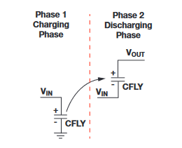
A: Charge pumps use an electronic switch to control the connection of a supply voltage across a load through a capacitor in a two-step process, Figure 2. in the first step, a capacitor is connected across the DC input supply, charging it to that same voltage. In the second step, the switches are used to reconfigure the circuit so that the capacitor is in series with the supply and the load. Now, the voltage across the load is doubled, as it is the sum of the original supply and the capacitor voltages. The switching action is repeated. Additional regulation is needed to smooth out the pulsed voltage at the output.
Q: How fast does this switching usually occur?
A: An external or secondary clock circuit drives the switching, typically at tens of kHz up to several MHz. A higher frequency minimizes the amount of capacitance required, as less charge needs to be stored and replenished in a shorter cycle. However, higher frequencies can also have higher losses, so there’s a tradeoff.
Q: What ratios are available between input and output voltages?
A: By adjusting the switching duty cycle, charge pumps can deliver double, triple, half, and scaled (such as ×3/2, ×4/3). With some rearrangement of the topology, they can also invert or reduce the output voltage (called buck mode), but that is not relevant to here.
Q: What are some of the general performance attributes of the charge pump?
A: They can be efficient (80-90%) but only when the components are sized for a specific load current. If the load current changes, the efficiency drops. Also, there are losses in the switching circuity which increase as the switching frequency increases; on the other hand, the output ripple is far less at higher frequencies, so the output filtering is simplified.
Q: Where are charge pumps used?
A: They are widely available and used as standalone voltage-boost ICs or as part of buck-boost regulator ICs. They are also often embedded within an IC to provide the higher voltages needed by some (not all) internal functions or external I/O (such as enabling a 3-V RS-232/423 interface IC to provide a 5-V or even 12-V drive. The capacitors are usually external to the IC.
Q: Is the charge pump the only option? What about that “flying capacitor?”
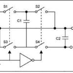
A: No, the switched capacitor is just one of several related capacitor-based variations which use electronic switches to transfer charge between an input-side capacitor and an output-side capacitor (Figure 3).

The flying-capacitor principle is this: as the charge q in a circuit is unchanged (let’s assume there is no load, for now) then the input-side charge q = C1 × V1. Then, if this charge is switched to another capacitor on the output side, q flows to that capacitor but is unchanged, and thus the voltage on the second capacitor changes, as q now equals C2 × V2. If the output-side capacitor is smaller than the input-side one, the output-side voltage will be higher than the input-side voltage.
Q: This almost sounds like something for nothing, but is it?
A: No, it is not. As charge is “drained” from the output side by the load, the capacitor’s voltage will decrease. To correct this, the input-to-output action must be repeated at a high enough rate to replenish the lost charge.
Q: Can either the transformer or capacitor schemes be used for transforming, say, 10 or 100 V to thousands of volts?
A: In theory, yes; but in practice, they cannot be used without major adjustments, as the high-voltage world has some unique issues.
Part 2 of this FAQ will look at how clever schemes, based primarily on diodes and capacitors, are used to develop those much-higher voltages.
References
- EE World Online, “FAQ: What is a charge pump and why is it useful? (Part 1)”
- EE World Online, “FAQ: What is a charge pump and why is it useful? (Part 2)”
- Wikipedia, “Flyback converter”
- Spellman High Voltage Electronics Corporation, “High Voltage Reference Manual”
- Spellman High Voltage Electronics Corporation, “What is a voltage multiplier?”
- All About Circuits, “Voltage Multipliers (Doublers, Triplers, Quadruplers, and More)”
- Instructables, “High Voltage Multiplier”
- MIT, “MIT engineers fly first-ever plane with no moving parts”
- MIT Electric Aircraft Initiative, “MIT engineers fly first-ever plane with no moving parts in propulsion system”
- Georgia State University Hyperphysics, “Cockroft-Walton Accelerators”
- Wikipedia, “Cockcroft–Walton generator”
- Wenzel Associates, TechLib, “Cockcroft-Walton voltage multipliers”



Leave a Reply