The high electrical currents of fast charging are forcing designers to invent standard techniques for predictably modeling heat and cooling.
Dr. Michael Ludwig, T&C Core Technologies, TE Connectivity

The only way electric vehicles (EVs) will ever catch on is if consumers can charge them up quickly. Consequently, manufacturers are developing high-power charging (HPC) schemes which would enable users to get 300 km of range in less than 10 minutes. The current generation of dc chargers work with 50 kW and 125 A in majority, but the next generation is expected to involve up to 350 kW. Simultaneously, designers of EVs are trying to boost range by reducing component weight and increasing efficiency. All of these changes will directly impact the design of the vehicle’s energy backbone.
But the drive to reduce weight and improve electric drivetrain performance makes thermal issues tougher to manage. Higher electrical currents generate more heat, while lighter and smaller components make heat sinking more problematic.

Thermal considerations for future EV charge cables will only grow more stringent. Connectors attached to cables with an effective cross-section of 95 mm2 are carrying loads of up to about 400 A in lab conditions. However, they are not generally rated to be used under these loads. The current-carrying capability is derated to compensate for degradation over a lifetime and provide a safety margin for application-specific characteristics that might impact the cooling behavior. Derating factors vary regionally between 0.8 and 0.9.
Aluminum wires are appealing to automakers as they are beneficial in regard to weight and cost. However, they should be used for smaller diameter cables and wiring with lower electrical loads as the characteristics of the material and the interconnection to aluminum needs to be carefully thought-out for thermal considerations when joule heating becomes a dominant phenomenon.
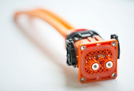
These complications certainly affect terminals and connectors used to handle EV power. Traditionally, terminals and connectors have power ratings derived from derating measurements such that the terminals and connectors operate at less than their maximum capabilities to prolong operating life. This practice has led to robust designs that have significant safety margins. But this practice doesn’t consider common applications in which the plug mounts to an aggregate; the interactions with busbars; and the transient behavior of components.
TE Connectivity is collaborating with ZVEI, a leading German association for electrical and electronic manufacturers, to develop a framework that overcomes these limitations. The framework will enable effective evaluation of how wires and connectors perform when they are integrated in relevant applications, while also considering their specialized boundary conditions.
Today’s testing models have limitations. Typical applications for high-voltage (HV) connectors in EVs involve mounting one side of the connector to a busbar, such as at the battery, the inverter, or the onboard charger. This application differs strongly from the derating test scenario in which cables 1.4 m long are applied to both sides of the connector.
In addition to boundary conditions, the ambient environment plays a dominant role in many applications. Cooling strategies employing forced convection can boost current carrying capability, whereas cable ducts hinder convection. The derating scenario has limited usefulness because it considers only free convection when deriving HV connector specifications.
In the characterization of current-carrying capabilities, conditions based on derating consider only steady-state temperatures. However, the transient behavior of components is actually more important.

To illustrate, when a current of 400 A is applied to a connector through 1.4-m of cable, it takes more than an hour for the assembly to reach a steady state. In real life, a high-power charging solution will complete the charging operation within 10 minutes. So charging finishes long before components reach a steady-state temperature.
In addition, real driving cycles often are characterized by highly dynamic load changes. These changes produce high-amplitude current peaks that last for a few seconds. The need to accommodate these peaks is an application-specific requirement that doesn’t show up in conventional specification methods.

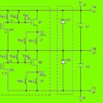
The new approach to evaluating HV connector performance uses thermal equivalent circuits (TEC) which are analogous to electrical equivalent circuits. These TECs consist of thermal resistances, the equivalent to ohmic resistances, and thermal capacities, the equivalent to capacitors.
Heat is generated at various positions within the TEC according to the law of Joule heating. Additionally, the modeled part interacts with the ambient environment via radiation and convection at the surface. A third and dominant heat transfer mechanism is heat conduction towards the aggregate system and individual cables.
Values for the thermal resistors can be derived from geometrical considerations and specific thermal resistance, while the capacitor values can be estimated based on specific heat capacity and weight. These considerations are valid for primary heat transport along the current-carrying path. However, another approach is needed to derive parameter values for heat transport mechanisms involving isolation and shielding. Consequently, there is a second approach that relies on data generated by finite element methods (FEM) and empirical data generated on a dedicated test bench.
A harmonized simulation model
ZVEI is defining harmonized TECs for connectors and cables. As a result, products are characterized not only by derating curves but also by a parameter set describing the component behavior. Engineers can use component TECs and parameter sets in a modular fashion to build thermal models and customize then to specific application conditions.

A harmonized simulation model helps find the best thermal solution and analyze the effects of various influencing factors. Influencing factors, which can be adjusted easily, typically include current profiles linked to charging or driving cycle data, parameters which underly aging effects, effects tied to wire length or cross-section, application of a radiator to improve convection, and other variables.
A non-obvious advantage of this method is that it makes it possible to measure the temperature of inaccessible components. Parts with low mass react immediately to thermal stresses before conduction can cool them off. Measurement of physically inaccessible components lets manufacturers better understand overall temperature generation and distribution and find performance bottlenecks without the need for extensive FEM simulations.
The TEC is simple enough that there are no special hardware requirements to make it work. Simulations containing models for an aggregate, a harness, and a connector can run within a few seconds, simulating a transient current profile over a few hours with a resolution of seconds or even less. From a software perspective, any SPICE simulation environment can be used as well as any physical modeling software.
In a nutshell, the evolution of EVs will require new approaches to developing and testing high-power connectors which cannot be addressed using conventional specification methods. A methodology based on thermal equivalent circuits helps designers assess transient behavior stemming from highly dynamic driving profiles or short high-power charging applications.
TE Connectivity is collaborating with ZVEI to develop a general guideline to standardize models for both connectors and for shielded and unshielded cables which will enable more accurate testing and fit-for-purpose engineering. The thermal analysis reflects specific properties of various connectors through use of an intrinsic parameter set applied to the standardized models.
Manufacturers can execute simulations using any SPICE or physical simulation software on an office PC or desktop. The ability to do efficient computations also lets teams simulate large systems, including aggregates, connectors, and wires, as well as the thermal response to current profiles over a few hours, as recorded in real driving cycles.


Leave a Reply