
by Majeed Ahmad
High temperatures and operating conditions outside the safe operating area can sabotage MOSFETs used in switching circuits.
The MOSFET (metal-oxide-semiconductor field-effect transistor) is a primary component in power conversion and switching circuits for such applications as motor drives and switch-mode power supplies (SMPSs). MOSFETs boast a high input gate resistance while the current flowing through the channel between the source and drain is controlled by the gate voltage. However, if not appropriately handled and protected, the high input impedance and gain can also lead to MOSFET damage caused by over voltage or too-high current.
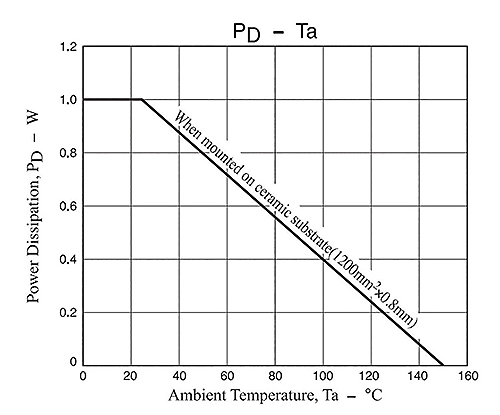
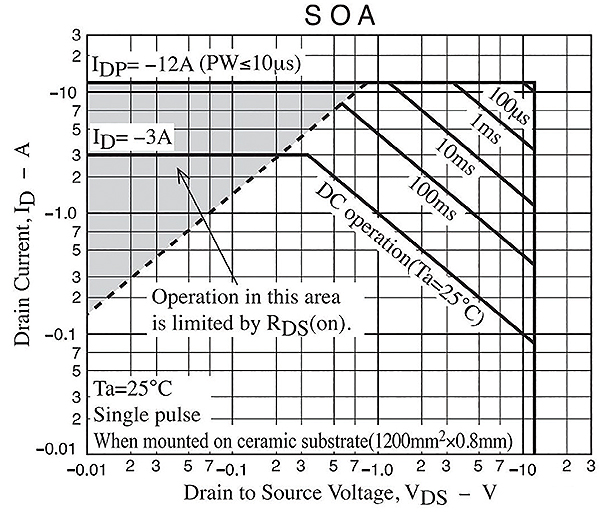
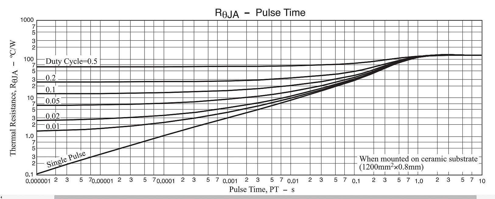
First a few basics about avoiding MOSFET damage. Obviously, Vgs and Vds must both be within limits. The same for current, Id. There is also a power limit given by the maximum junction temperature. Basic values for the upper maximum on these parameters are given in the safe operating area (SOA) graph in the MOSFET datasheet. But it turns out, other thermal limits can apply. The SOA graph, for example, generally assumes an ambient temperature of 25° C with a specific junction temperature, usually below 150° C. But there are a variety of conditions that may cause high thermal gradients that may lead to expansion and cracking of the MOSFET die.

One factor to consider in this regard is that MOSFET thermal resistance is an average; it applies if the whole die is at a similar temperature. But MOSFETs designed for switch-mode power supplies can experience a wide temperature variation over different areas of their die. Optimized for on/off switching, they typically don’t work well in their linear region.
A typical failure mode for a MOSFET is a short between source and drain. In this case, only the source impedance of the power source limits the peak current. A common outcome of a direct short is a melting of the die and metal, eventually opening the circuit. For example, a suitably high voltage applied between the gate and source (VGS) will break down the MOSFET gate oxide. Gates rated at 12 V will likely succumb at about 15 V or so; gates having a 20-V rating typically fail at around 25 V.
All in all, exceeding the MOSFET voltage rating for just a few nanoseconds can destroy it. Device manufacturers recommend selecting MOSFET devices conservatively for expected voltage levels and further suggest suppressing any voltage spikes or ringing.
Too little gate drive
MOSFET devices are designed to dissipate minimal power when turned on. And the MOSFET must be turned on hard to minimize dissipation during conduction, otherwise it will have a high resistance during conduction and will dissipate considerable power as heat.
Generally speaking, a MOSFET passing high current will heat up. Poor heat sinking can destroy the MOSFET from excessive temperature. One way of avoiding too-high current is to parallel multiple MOSFETs so they share load current.
Many P- and N-channel MOSFETs are used in topologies involving an H- or L-bridge configuration between voltage rails. Here, if the control signals to the MOSFETs overlap, the transistors will effectively short-circuit the supply. This is known as a shoot-through condition. When it arises, any supply decoupling capacitors discharge rapidly through both MOSFETs during every switching transition, causing short but large current pulses.
The way to avoid this condition is to provide a dead time between switching transitions, during which neither MOSFET is on.
Over-currents even for a short duration can cause progressive damage to a MOSFET, often with little noticeable temperature rise before failure. MOSFETs often carry a high peak-current rating, but these typically assume peak currents only lasting 300 µsec or so. It is particularly important to over-rate MOSFETs for peak current when they switch inductive loads.
When switching inductive loads there must be a path for back EMF to freewheel when the MOSFET switches off. Freewheeling is the sudden voltage spike seen across an inductive load when its supply voltage is suddenly interrupted. Enhancement mode MOSFETs incorporate a diode that provides this protection.
High-Q resonant circuits can store considerable energy in their inductance and capacitance. Under certain conditions, this high energy causes the current to freewheel through the internal body diodes of the MOSFETs as one MOSFET turns off and the other turns on. (An intrinsic body diode is formed in the body-drain p-n junction connected between the drain and source. In N-channel devices, the body diode anode connects to the drain. The polarity is reversed in P-channel MOSFETs.) A problem can arise because of the slow turn-off (or reverse recovery) of the internal body diode when the opposing MOSFET tries to turn on.
MOSFET body diodes generally have a long reverse recovery time compared to the performance of the MOSFETs themselves. If the body diode of one MOSFET conducts when the opposing device is on, a short circuit arises resembling the shoot-through condition. The solution to this problem involves a Schottky diode and a fast-recovery diode. The Schottky diode connects in series with the MOSFET source and prevents the MOSFET body diode from ever being forward biased by the freewheeling current. The high-speed (fast recovery) diode connects in parallel with the MOSFET/Schottky pair. It lets the freewheeling current bypass the MOSFET and Schottky completely. This ensures the MOSFET body diode is never driven into conduction.
Transitions
A MOSFET dissipates little energy during its steady on and off states, but it dissipates considerable energy during times of a transition. Thus, it is desirable to switch as quickly as possible to minimize power dissipated. Because the MOSFET gate is basically capacitive, it requires appreciable current pulses to charge and discharge the gate in a few tens of nanoseconds. Peak gate currents can be as high as an ampere.
The high impedance of MOSFET inputs can lead to stability problems. Under certain conditions, high-voltage MOSFETs can oscillate at high frequencies because of stray inductance and capacitance in the surrounding circuit (frequencies usually in the low megahertz range). Device manufacturers recommend that a low-impedance gate-drive circuit be used to prevent stray signals from coupling to the MOSFET gate.
References
ON Semiconductor
onsemi.com


This is an incredible article , it gives a loud able knowledge how mosfet works as a switch and simple preventative measures….
……. this is the article I have been missing….
this is a ton of info on Mosfets, waohh..after applying one or two of the preventive measures, your circuit should work fine
Rare find discussing about what would happen if MOSFET is subjected to its limits. Very good reference for design and safety.
Another thing to look out for is the over voltage from the curcuit ringing. To prevent this a snubber could be added or a zener diode, to the MOSFET never experiences over voltage
article has crisp and crystal clear details on MOSFET.
Thank you for this article. I enjoyed reading it!
I repaired a 300 W conventional inverter 12V to 230V, and replaced 1 set of 2 out of 2 sets of 2 of IRF840 MOSFETs each in the process. The original fault was a broken MPSA44 and also a parallel diode (1N4148) to one of the MOSFETs, which I both replaced. It then worked fine when I plugged in 1 laptop computer. When I plugged in a 2nd laptop the inverter suddenly stopped working and the red LED flashed (fault). I then switched off, and then switched on without load, and the 2 MOSFETs that I had replaced both short-circuited, blowing the external fuse as a result. When measuring other parameters with the multimeter, everything seemed alright. I’m now out of MOSFETs, and don’t know what else could be broken.
Inverters power surge, overload and sudden removal of high load, lightening, and short circuit is still a problem in inverters technologies. Maybe more protection for these mentioned
On two occasions I have removed a shorted mosfet from a power amp and then successfully run the amp on a reducsed load with no problem.
I then replaced the faulty mosfet with a new and identical mosfet and powered up the amp resulting in the switchmode power mosfets failing and blowing the mains fuse. Does this mean I have dameged the new mosfets during fitting by failing to observe antistatic management?
Thank you for this insightful article on MOSFET, I’ve been looking for where I can get this and more.
I have these inverter boards that usually have faults on MOSFETS
I have this model of MOSFET on some of the inverters HY3215W (A1M07HA1A) can anyone here give me more knowledge on the causes of failure of these MOSFETs. Thank you
A master of the craft. Thanks, Majeed Ahmad! Thank you for sharing so openly, this alone puts your above all the rest, including the all the high-strung experts. 🙂
Does the potential for shoot through only occur when both n and p channel mosfets are used ?