• Skip to primary navigation
  • Skip to main content
  • Skip to primary sidebar
  • Skip to footer

Power Electronic Tips

Power Electronic News, Editorial, Video and Resources

  • Products
    • Power Supplies
    • AC-DC
    • DC-DC
    • MOSFETS
    • Power Management
    • Battery Management
    • RF Power
    • Resistors
    • Capacitors
    • Magnetics
    • Transformers
  • Applications
    • LED Lighting
    • Rack Mount
    • Wireless
  • EE Forums
    • EDABoard.com
    • Electro-Tech-Online.com
  • EE Learning Center
  • Video
    • EE Videos
    • TI Power Videos
    • Teardown Videos
  • Resources
    • Design Fast
    • eBooks / Tech Tips
    • FAQ
    • LEAP Awards
    • Podcasts
    • Webinars
    • White Papers

How bidirectional converters speed the design of dual-battery automotive systems

August 12, 2019 By Lee Teschler Leave a Comment

New standards for combined 48-V/12-V vehicles dictate stringent tests for overvoltages and currents that new converter ICs can help meet.

Tony Armstrong | Analog Devices Inc.
The 48/12-V automotive battery system is just around the corner. Most major automobile manufacturers have been perfecting such systems for past few years, and it is evident that their first implementations will be relatively near term.

 12-48 V systems
The typical 12 and 48-V electrical system planned for emerging EVs and hybrids divides electrical loads into light and heavy-duty categories, with the conventional 12-V SLA battery handling infotainment and similar tasks while the 48-V battery powers big loads. The 48-V part of the system is designed so it is generally isolated from anyone but qualified auto technicians. It should also be said that there is still some debate about exactly what loads will go on the 12-V rather than the 48-V part of the system. Nevertheless, it is clear from the 48/12-V architecture that the bidirectional dc/dc converter that links the two electrical systems is a critical component key to the efficient operation of the entire vehicle.

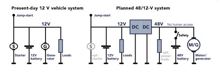
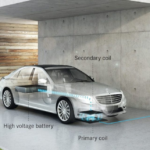
The typical 48/12-V system consists of two separate branches of power. The traditional 12-V bus uses a conventional sealed lead-acid (SLA) battery to handle traditional systems such as infotainment, lighting, and windows. The new 48-V system will support heavier loads such as the starter/generator, A/C compressors, electric turbochargers, and regenerative braking. Vehicle electrical components will either run off the 48-V Li-ion battery or the 12-V SLA – but not both.

The point of the 48-V system is to reduce weight in the wiring harness. The higher voltage allows use of less current for the same amount of power and thus makes it possible to employ lighter, lower-gauge wiring. The advantage becomes clear from the fact that high-end vehicles today can carry more than 4 km of wire.

The move to 48/12-V systems is a necessary and crucial step in the long and arduous journey to the fully autonomous passenger vehicle. The transition doesn’t mean the 12-V battery is going away; there are far too many legacy 12-V systems in the installed vehicle base for this to happen anytime soon.

Nevertheless, use of 48/12-V systems introduce complexities. There must be two separate charging circuits for these individual batteries because of their respective chemistries. Additionally, there must be a mechanism to safely move charge between them.

While dual batteries certainly complicate the design of the various vehicle electrical sub-systems, there are advantages to be gained. For one thing, having two batteries allows for redundancy should one fail. And according to some auto makers, a 48-V electrical system results in a 10-15% gain in fuel economy for internal combustion engine (ICE) vehicles, thus reducing CO2 emissions. Moreover, future vehicles that use a dual 48/12-V system will enable the integration of electrical booster technology that operates independently of the engine load, thereby improving acceleration. Such compressors are already in the advanced stages of development and will reside between the induction system and the intercooler, using the 48-V rail to spin-up their turbos.

Meanwhile, the proliferation of new electrical systems and connectivity within vehicles has brought the 12-V electrical system to its usable power limit. These changes, coupled with increased demands for power, have created the need for supplementing the 12-V SLA battery system with its 3-kW max output.

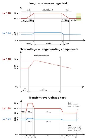
New automotive standards spell out some facets of how 48/12-V systems must function. A newly proposed automotive standard, known as LV148, calls for a secondary 48-V bus that works with the existing 12-V system. In 2011, this standard was adopted by the Big Five German automakers – Audi, BMW, Daimler, Porsche, and Volkswagen – and spells out electrical requirements and test procedures for 48-V components. According to LV148, the 48-V rail is to include an integrated starter generator (ISG) or belt start generator, a 48-V lithium-ion battery, and a bidirectional dc/dc converter able to deliver 10 sec of kilowatt-level energy from the 48-V and 12-V batteries combined. This technology is aimed at conventional ICE automobiles, as well as hybrid electric and mild hybrid vehicles.

Integrating 48/12-V battery systems

LV148 requires that the 12-V bus continuously power the ignition, lighting, infotainment and audio systems. It uses the 48-V bus to power bigger loads — active chassis systems, A/C compressors, and so forth, and to participate in regenerative braking.

LV148 tests
It becomes clear why features such as dynamic current limiting and voltage protection are important in automotive bidirectional dc/dc converters by examining LV148, a standard adopted by the Big Five German automakers that spells out electrical requirements and test procedures for 48-V components. Among them are tests for transient overvoltage, long-term overvoltage, and overvoltage on regenerative components (graphs courtesy, AMETEK Compliance Test Solutions). These kinds of conditions, and many more along the same lines, are what the bidirectional dc/dc converter in any 48/12-V system is likely to encounter.
The addition of a 48-V supply network will impact other electrical components as well. Electronic Control Units (ECUs), for example, will need to work at a higher voltage. This, in turn, will necessitate that manufacturers of dc/dc converters introduce specialized ICs to enable this higher-power transfer.

In this regard, Analog Devices’ Power by Linear (PbL) group designed and developed dc/dc converters able to transfer higher levels of energy with high efficiency, thus conserving energy while simultaneously minimizing thermal design aspects.

Specifically, 48/12-V systems call for a bidirectional step-down and step-up dc/dc converter that spans the two voltages. The converter plays a role in charging either of the batteries while simultaneously allowing both batteries to supply current to the same load if that’s what is required.

The first 48/12-V dual battery dc/dc converters to come off the drawing boards used different power components to step-up and step-down the voltage. However, ADI’s recently introduced LT8228 bidirectional dc/dc controller uses the same external power components for the step-up conversion as for step-down conversion. This part is a 100-V bidirectional constant-current or constant-voltage synchronous buck or boost controller with independent compensation networks.

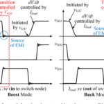
The LT8228 automatically determines the direction of power flow or the direction can be externally controlled. Input and output-protection MOSFETs protect against negative voltages, control inrush currents, and provide isolation between terminals under fault conditions such as shorts in the switching MOSFETs. In step-down mode, protection MOSFETs prevent reverse current. In step-up mode, the same MOSFETs regulate the output inrush current and use an adjustable timer circuit breaker to protect themselves.

The LT8228 configured in a simplified bidirectional battery backup system. The LT8228 mode of operation is externally controlled through the DRXN pin or automatically selected. In addition, the LT8228 has protection MOSFETs for the V1 and the V2 terminals. The protection MOSFETs provide negative voltage protection, isolation between the input and output terminals during an internal or external fault, reverse current protection and inrush current control. The LT8228 provides input and output current limit programming in buck and boost mode operation using four pins, ISET1P, ISET1N, ISET2P and ISET2N. The controller also provides independent input and output current monitoring using the IMON1 and IMON2 pins. Current limit programming and monitoring is functional for the entire input and output voltage range of 0 to 100 V. Additional features include a feedback voltage tolerance = ±0.5% over temperature; self-test, diagnostics and fault reporting; programmable fixed or synchronizable switching frequency from 80 kHz to 600 kHz; and programmable soft-start and dynamic current limit.
The LT8228 implements bidirectional input and output current limiting as well as independent current monitoring. Masterless, fault-tolerant current-sharing allows LT8228 chips to work in parallel and to be added or subtracted while maintaining current sharing accuracy. Internal and external fault diagnostics and reporting are available via separate pins (FAULT and REPORT). Each LT8228 regulates to the average output current, thus eliminating the need for a master controller. When an individual LT8228 is disabled or in a fault condition, it stops contributing to the average bus, making the current sharing scheme fault tolerant. The LT8228 sits in a 38-lead TSSOP package.

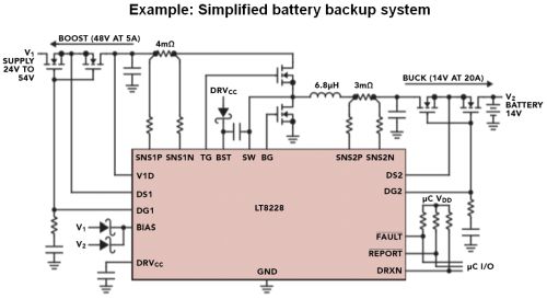
The LT8228 controller provides a step-down output voltage when in buck mode or a step-up output voltage when in boost mode. The input and output voltage can be set as high as 100 V. In applications such as battery backup systems, the bidirectional feature allows the battery to be charged from either a higher or lower voltage supply. When the supply is unavailable, the battery boosts or bucks power back to the supply.

To optimize transient response, the LT8228 has two error amplifiers, one for boost mode, the other for buck mode with separate compensation pins. The controller operates in discontinuous conduction mode when reverse inductor current is detected for light load conditions.

The LT8228 brings a new level of performance, control and simplification to 48/12-V dual battery dc/dc automotive systems. During starting or when the vehicle needs additional power, the LT8228 allows both batteries to supply energy simultaneously to the same load. Thus this bidirectional converter helps designers easily configure the 12-V and 48-V battery systems which will be required for the fully autonomous vehicles of the near future.

You may also like:

  • ISL78714 Li-ion battery management IC
    Li-ion battery management IC for hybrid and electric vehicles
  • Charging electric vehicles
    Charging electric vehicles, Part 2: The connections
  • GaN power devices
    GaN power devices, Part 2: Application
  • GaN power devices
    GaN power devices, Part 1: Principles
  • pcim
    Achtung! Power technology on display at PCIM Nuremberg

Filed Under: Converters, DC-DC, FAQ, Featured, Promoted features Tagged With: analogdevicesinc

Reader Interactions

Leave a Reply

Your email address will not be published. Required fields are marked *

This site uses Akismet to reduce spam. Learn how your comment data is processed.

Primary Sidebar

CURRENT DIGITAL ISSUE

Featuring 15 articles, the 2022 5G Handbook looks at private networks, timing, connectivity, latency, mmWaves, test, and other topics.

More from the digital archive

DesignFast

Component Selection Made Simple.

Try it Today
design fast globle

Subscribe to our Newsletter

The Power Electronic eNewsletter delivers breaking electronic and power component news, resources, product innovations and more.

Subscribe today

EE TRAINING CENTER CLASSROOMS

EE Classrooms

RSS Current EDABoard.com discussions

  • Manifest in Git bitbucket
  • What's the deal with all these "MPPT" IC's with no current sense?
  • Photovoltaic MOSFET Drivers - Voltage Rating
  • Impedance requirement for SDRAM signals
  • A circuit that can adjust a resistance and probing a voltage node

RSS Current Electro-Tech-Online.com Discussions

  • How to quickly estimate lead acid battery capacity ?
  • IRS2453 the H circuit
  • Ampro 16mm Stylist projector woes.
  • Finally switched to Linux.
  • Multistage BJT amplifier

Footer

EE World Online Network

  • DesignFast
  • EE World Online
  • EDA Board Forums
  • Electro Tech Online Forums
  • Connector Tips
  • Microcontroller Tips
  • Analog IC Tips
  • Sensor Tips
  • Test and Measurement Tips
  • Wire and Cable Tips
  • 5G Technology World

Power Electronic Tips

  • Subscribe to our newsletter
  • Advertise with us
  • Contact us
  • About us
Follow us on TwitterAdd us on FacebookFollow us on YouTube Follow us on Instagram

Copyright © 2022 · WTWH Media LLC and its licensors. All rights reserved.
The material on this site may not be reproduced, distributed, transmitted, cached or otherwise used, except with the prior written permission of WTWH Media.

Privacy Policy