
The reverse connection of a circuit to its DC power source, whether it’s a battery or power supply, can damage and even destroy the electronics. For this reason, many connectors are “keyed” to ensure correct connection. But there are many connections which are directly hard-wired using wires inserted into screw terminals, or ring or spade lugs, and even the common car battery is not keyed. As a result, it is very easy to reverse the battery connection after repair or replacement, or accidentally touch the wrong terminals. The result is a reverse-polarity situation.
- Why is reverse connection now considered a more serious problem?
Several decades ago, when cars had no electronics except for the radio, and even the dashboard was mostly mechanical, the damage from reverse polarity would minimal, if at all. However, there are severe consequences in today’s cars, which are packed with sophisticated electronics including ADAS (Advanced Driver Assistance Systems) including backup camera, navigation, ABS (anti-lock braking), and anti-rollover sensing; high-end entertainment systems; GPS; wireless connectivity; and internal networks including Ethernet. The same applies to many other products which have gone from being barely electronic to loaded with electronics in the past few decades.
A reverse-connected battery or the transient due to a “load dump” (which momentarily reverses the voltage) could easily cause major, dangerous, and expensive failures across many of these subsystems, especially as the car battery can easily deliver several hundred amps to the load.
- What’s the obvious solution to preventing problems caused by a reverse-polarity connection?
The obvious solution is to use a diode in series with the supply rail wiring, Figure 1. A diode only allows current to flow in one direction and blocks reverse flow, thus preventing any current flow due to that reverse connection.
- What are the drawbacks to using a diode for reverse-polarity protection?
There are several:
- First, the diode must be rated for the full forward current, including its peak value. This can easily be several hundred amps in a car (when cranking) and close to that when all the modern electronics are in use. Therefore, a large and costly diode is needed, and the physical connections to this diode must be fairly hefty; again, that’d size and cost. Alternatively, smaller diodes can be used at each subcircuit or circuit board, but some of these still have large currents.
- Second, the diode must be “rugged” and capable of adequate performance at high temperatures (especially if under the hood) and it must accommodate the various surges and spikes of an automobile (or other system’s) electrical system.
- Third, there’s the unavoidable voltage drop of about 0.3 to 0.7 V across the diode (depending on the diode type). When the DC rail is only a few volts of potential (such as the 12-V nominal rail in a car), that’s a lot of potential to lose.
- Finally, the on-resistance of the diode, although only a few milliohms, translates to large thermal dissipation, which is both a waste in itself and also represents heat which must be managed.
- What’s a better solution?
Fortunately, active devices with clever topologies provide an alternative. The “smart diode” is an active device which provides diode functions, but in a better way. For example, the LM74610-Q1 Smart Diode Controller from Texas Instruments is a two-terminal device (like a diode), with an anode and cathode. It also contains an integrated charge pump to provide gate drive to an associated NFET device, Figure 2.
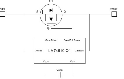
- How does this implement the reverse-polarity protection function?
The LM74610 drives an external MOSFET to emulate an ideal diode rectifier when connected in series with a power source. Under normal operating conditions, the transistor is turned on and so there is very low dissipation. However, if the voltage is reversed, The LM74610-Q1 responds in less than 8 μsec (important for protecting against load-dump transients).It can tolerate reverse voltages up to 45 V, exceeding the automotive required overvoltage range. An interesting advantage of this scheme is that it is not referenced to ground (there is no conduction path) and thus has zero quiescent current (Iq).
- Where is the smart diode function placed?
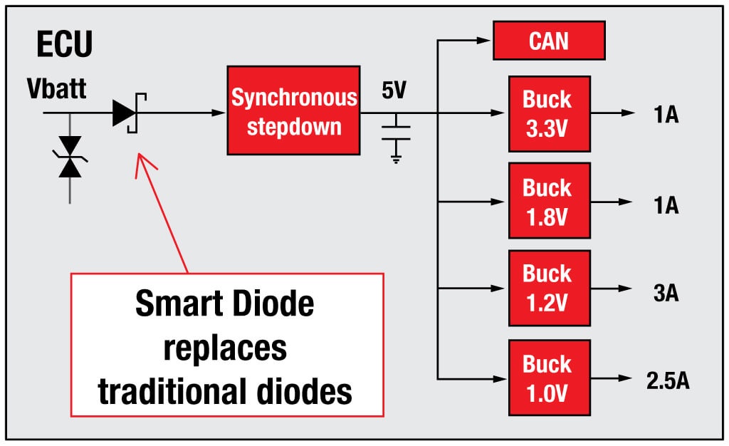
Since this IC is a tiny 8-lead, 3 mm × 5 mm VSSOP-8 package, it (and the associated FET) are usually placed on each of the various circuit boards within the product; if it’s an automobile, there will be many such smaller circuit boards located under the hood, in the driver’s console, and in other locations. Rather than use a single, system-wide protective device, using highly localized protection is more manageable from a cost and benefit perspective in many cases, and ensures that each circuit board is protected.
Leave a Reply