
Magnetics is a key technology for sustainable power conversion, electric vehicle motors, motion sensing and control in various medical, industrial, and consumer applications, and advanced data storage technologies. Advances in magnetics often provide the foundation for advances in electronic technologies and devices.
This FAQ presents the basics of magnetic field lines and field strength, looks briefly at the difference between a magnetic field and flux, puts the concepts of field and flux together in a hysteresis loop that illustrates many of the important characteristics of magnetic materials, reviews magnetic domains that are the source of fields and flux, and closes by presenting recent developments related to spintronics and magnetic domains.
Magnetic field
The electromagnetic energy that transfers magnetic force is the magnetic field (B). It’s illustrated using field lines that, by convention, always run from the north to the south pole of a magnet. They then flow through the magnet to the north pole, creating a closed-loop system (Figure 1). The stronger the field, the stronger the magnetic force. To illustrate relative field strengths, more field lines are used to show stronger fields. The strength of a magnetic field (H) is measured in ampere meters (A/m) or oersteds. An oersted is 1000/4π (about 79.5775) amperes per meter. For example, an H-field of about 1 oersted field is created inside a solenoid wound with 79.58 turns of wire per meter carrying 1 A.

Magnetic field vs. magnetic flux
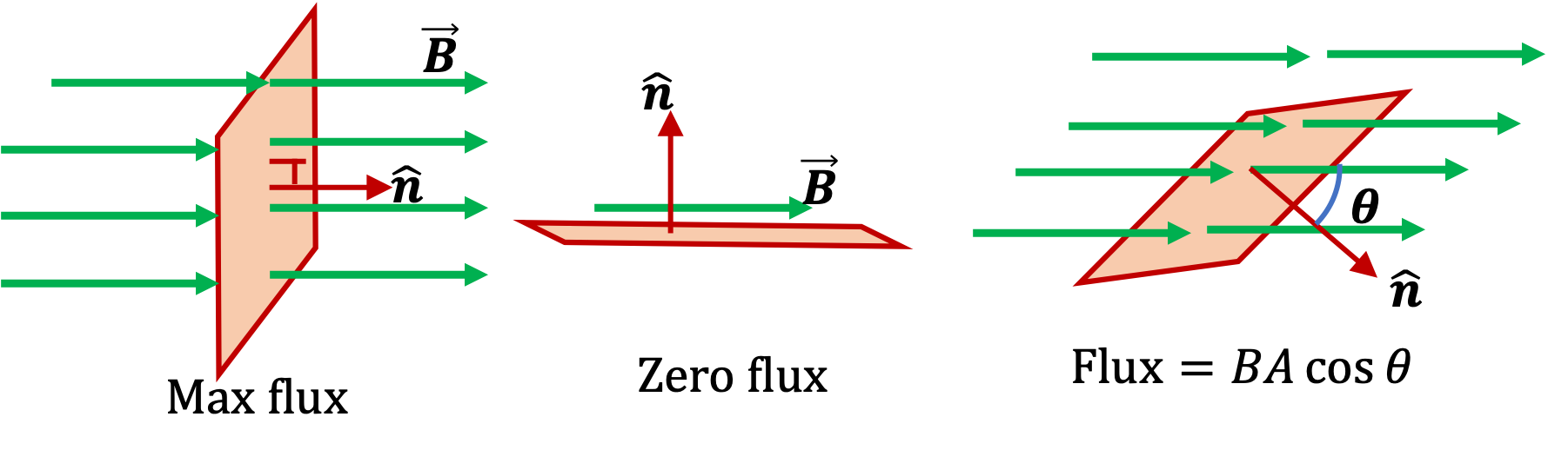
Magnetic flux (Φ or ΦB) and magnetic field are related concepts. Magnetic flux quantifies how much magnetic field passes through an area. ΦB is the surface integral of the normal component of the field vector B over that surface. The angle at which the field vectors (field lines) intersect the measured area is important. If a field is parallel to a surface, there will be no flux. Maximum flux is generated when the field is perpendicular to the surface. If the surface is at an angle, θ, to the field vectors, the flux can be stated as ΦB = BAcosθ, where A = the area (Figure 2). Magnetic flux density, also called magnetic induction, is often denoted by “B” and is quantified in teslas (T).
Putting field and flux together in a loop
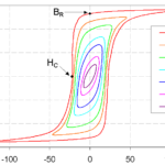
The specific magnetic properties of various materials result in different relationships between the magnetic induction (B) that the material is exposed to and the resulting magnetic field strength (H). A plot of B on the vertical axis versus H on the horizontal axis is called a B-H loop or a hysteresis loop. It specifically applies to ferromagnetic and ferrimagnetic materials often used in electronic applications. A hysteresis loop is produced by changing the magnetizing force, H, and measuring B’s resulting magnetic flux (Figure 3). The line from point “a” to point “b” in the first quadrant of the figure illustrates the B-H line for a material that has been thoroughly demagnetized or, for the first time, a new piece of material is magnetized.
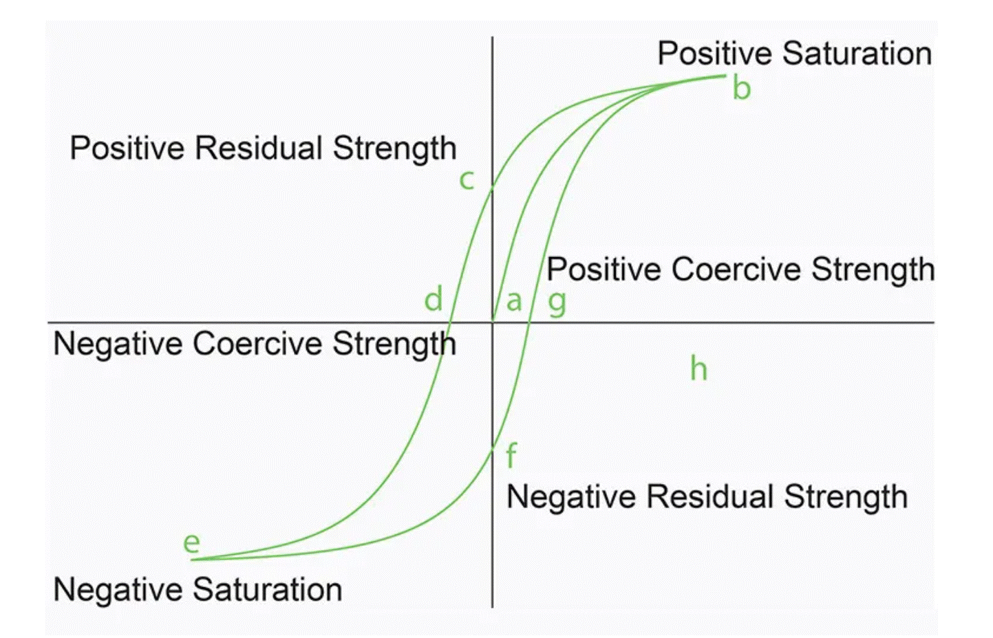
The measurement convention is to increase H and track the increase in B, traveling along the hysteresis curve in a counterclockwise direction. Once the material has become magnetically saturated at point “b,” the magnetizing force begins decreasing, reversing its polarity at point “c” and continuing to grow stronger in the opposite direction until reverse saturation is reached at “e.” Hysteresis curves are useful in determining several properties of magnetic materials, including:
- Retentivity, BR, measures the residual flux density when the magnetizing force is removed after achieving saturation. It’s the value of B at point c on the hysteresis curve.
- Residual Magnetism or Residual Flux measures the magnetic flux density that remains in a material when the magnetizing force is zero. Residual magnetism and retentivity are the same when the material is magnetized to saturation. However, the level of residual magnetism is often lower than retentivity when the magnetizing force did not reach saturation.
- Coercive Force, HC, is the amount of reverse magnetic field applied to a magnetic material to make the magnetic flux return to zero. It’s the value of H at point ‘d’ on the hysteresis curve.
- Permeability, µ, describes how easy it is to magnetize a material and quantifies the relationship between B and H, B=μH.
- Reluctance, S (or Rm), measures the opposition that a ferromagnetic material has to a change in a magnetic field. Reluctance is obtained by dividing the length of the magnetic path l by the permeability times the cross-sectional area A: S = l/μA.
Where do flux and force come from?
Atoms in ferromagnetic, ferrimagnetic, and antiferromagnetic materials are organized into regions called magnetic domains that are the source of magnetic flux and force (Figure 4). Paramagnetic and diamagnetic materials do not have magnetic domains. In paramagnetic and diamagnetic materials, the dipoles align in response to an external field but do not spontaneously organize to create domains.
When cooled below their Curie temperature, ferromagnetic, ferrimagnetic, and antiferromagnetic materials spontaneously divide into magnetic domains. A magnetic domain is a region within a magnetic material where the magnetic moments of individual atoms are aligned and point in the same direction. The magnetization within each domain points in a uniform direction, but the magnetization of different domains may point in different directions.
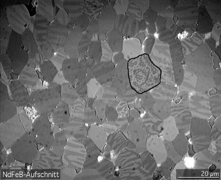
Magnetic domains form to minimize the material’s internal energy. A large domain of ferromagnetic material with constant magnetization throughout will create a large magnetic field requiring a large amount of magnetostatic energy. By splitting into two domains, with the magnetization in each domain in opposing directions, the field strength is lower, and the amount of magnetostatic energy is reduced. Each of those domains can split into smaller domains with alternating magnetization directions, further reducing the field strength and the amount of magnetostatic energy.
What determines the equilibrium domain configuration?
The creation of magnetic domains results in the creation of domain walls separating the domains. At a domain wall, magnetic dipoles with magnetization pointing in opposite directions are next to each other in the adjacent domains. Dipoles naturally align in the same direction, and to keep them pointing in opposite directions in adjacent domains requires energy. That energy is called domain wall energy and is proportional to the area of the wall.
The difference between the reduced magnetostatic energy from smaller domains and the additional energy required to form the domain walls determines the net energy savings. The magnetostatic energy is proportional to the cube of the domain size, and the domain wall energy is proportional to the square of the domain size. As domains shrink, the net energy saved by the size reduction decreases. The optimal domain size is determined when the magnetostatic energy saved equals the additional energy needed to create the domain walls.
The process does not really consist of splitting into smaller and smaller domains. The equilibrium domain configuration appears spontaneously when a material is cooled below its Curie temperature. The study of magnetic domains is called micromagnetics.
Spintronics and domain walls
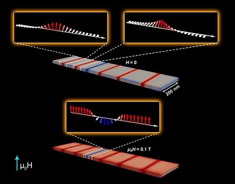
The electrons in each domain have the same magnetic orientation, and their spins point in the same direction. Spintronics refers to spin-charge coupling and is fundamentally different from conventional electronics. In addition to using the charge state, electron spins can be used as an additional degree of freedom, potentially improving the efficiency of data storage and transfer.
Controlling domain wall movement is challenging. Domain walls move unpredictably when domain size shrinks to support higher information storage densities. Further, different types of walls separate magnetic domains. Chiral domain walls have spin rotations that are left- or right-handed. When a magnetic field is applied, chiral domain walls move toward each other. The class of materials called chiral magnets has demonstrated the potential to mitigate unpredictable domain wall movements and reduce the random reversal of domains, including domain wall combination or annihilation (Figure 5). If further refined, that could support the development of high-density data storage technologies based on spintronics.
Summary
Understanding magnetic fields, flux, and domains can be important for developing more sustainable green energy systems, power conversion and energy storage and transportation systems, and improved sensors and controls for various medical, consumer, industrial, and other applications. The ability to control domain wall behavior could also have important implications for developing spintronics technologies, including high-density data storage.
References
Magnetic Domain, Wikipedia
Magnetic Flux, Physics Bootcamp
Scientists Take Control of Magnetism at the Microscopic Level, US Department of Energy
Understanding Hysteresis and BH Curves, Ideal Magnetic Solutions
What does “magnetic field” and “magnetic flux” mean?, Supermagnete


thank you for the information