
Thyristors are four-layer semiconductor switches with alternating layers of P- and N-type materials. While all thyristors share the same basic structure, the details of their implementation and packaging can be modified to meet the needs of specific applications.
This FAQ reviews basic phase control thyristor (PCT) operation, then looks at the use of bidirectional controlled thyristors (BCTs) and bidirectional phase control thyristors (BiPCTs) in utility-scale power conversion systems, and closes with a look at bypass thyristors (BTs) and asymmetric BTs designed to ensure the reliable operation and prevent explosions in high power modular multilevel converters.
PCTs are used as phase-controlled current ‘valves’ for high voltage ac-input power converters, mostly operating at ac line frequencies but sometimes at frequencies up to about 1 kHz. They can be found in power converters, battery chargers, resistance heaters, lighting controls, and industrial motor drives. While they can block very high voltages, they also have very low on-state resistances and can produce high-efficiency converters. PCT-based converters employ phase fired control (PFC), sometimes called phase angle control or phase cutting, to modulate the power through the device.
PFC is used with power sources that have modulated waveforms, such as the sinusoidal ac found on utility power grids. That’s in contract with pulse width modulation used to control power transfer on dc power buses. To implement PFC, it’s necessary to know the modulation frequency and cycle of the power source. That information makes it possible to switch the thyristor on at the correct point in the cycle to transfer the desired amount of energy. A PFC can synchronize with the modulation present at the input. Like a switched-mode power supply buck topology, PFC can only result in a maximum output level equal to the input minus any losses in the conversion process.
The proliferation of applications for PCTs has resulted in a wide range of devices optimized for various performance criteria such as low conduction losses, low forward voltage drop, or low stored charge. For example:
- PCTs with low conduction losses can be especially useful in crowbars, static switches, and some high voltage power supply designs
- PCTs with low switching losses are suited for bridge rectifiers and high-power drives.
- PCTs with low stored charge are designed for higher frequency power conversion applications.
Bidirectional phase control thyristors
A bidirectional control thyristor (BCT) consists of two thyristors integrated on the same silicon wafer with separate gate contacts. BCTs are designed to replace triacs in high voltage applications. Triacs can be used for voltages up to about 1 kV. Above that level, the required thickness of a triac makes uniform control of the device via a single gate impractical. The design of the gate structure is important in BTCs to achieve fast turn-on and prevent interference between the constituent thyristors. The device needs to be compact, but there needs to be adequate separation between the two thyristors to prevent the combined device from being destroyed by high dV/dt values that can cause uncontrolled triggering after commutation.
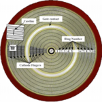
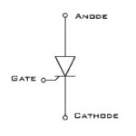
The bidirectional phase control thyristor (BiPCT) was developed to improve BCTs’ operational characteristics. A BiPCT has two thyristors in an anti-parallel configuration on a single wafer with separate gate terminals for each thyristor (Figure 2). As with a BCT, one of the gates turns on the current in the forward direction, and the other gate turns on the current in the reverse direction. Among the benefits of BiPCTs compared with BTCs are increased surge current ratings, reduced thermal resistance, and reduced cost through simplified fabrication. In addition to the gate design considerations in a BCT, a BiPCT uses interdigitation of the anode and cathode regions of both anti-parallel connected thyristors. When designing BCTs or BiPCTs, one challenge is to have a performance curve between the on-state voltage (VT) and the recovery charge (Qrr) for each of the integrated devices that are as close as possible to a single PCT device.

The use of BiPCTs delivers cost advantages in terms of smaller system volume of the active components and smaller snubbers and control circuits. The simplification of the thyristor valve assembly can result in 30% lower costs than discrete PCTs. Since there are fewer components, the reliability of a BiPCT-based thyristor valve assembly should be significantly higher than a similar assembly based on discrete PCTs, assuming that the BiPCT has similar reliability as a PCT.
Bypass thyristors
Reliability is a key requirement for utility-scale modular multilevel converters (MMCs). MMCs are expected to continue operation even in the event of the failure of one of the modules. BTs are sacrificial devices and were developed specifically to meet that need. A MMC is expected to provide serial redundancy and have the ability to reliability discharge the energy stored in a cell and short the cell’s terminals in the event of a fault. The stored energy in a high-power MMC is often large enough to rupture the housing of a conventional thyristor, resulting in external arcing, possible capacitor explosions, or ruptures of electrical connections. Thyristor faults are expected in these systems.
Before the availability of BTs, the cell terminals were shorted during a fault event using a mechanical switch. A mechanical solution adds to solution size and cost and can be unreliable. Bypass thyristors were developed to provide a lower cost and more robust option.
In normal operation, the BT is OFF and does not affect cell operation. The BT is instantly turned on to handle the energy surge when a fault occurs. In an MMC application, when a cell fails, the BT housing will not rupture even when experiencing currents as high as 363 kA and an I2t up to 217 MA2s. After a fault occurs, the BT can continue to operate as a stable short circuit (taking the bad cell out of operation) for over a year until the next scheduled maintenance occurs. At this time, the MMC is de-energized, and the faulty cell module can be replaced. For example, after a fault event, a typical BT can conduct 1,300 Arms with a voltage drop under 1.75 Vrms for over a year with no detrimental effects.
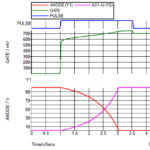
In addition to optimal device design, packaging is a key to achieving the levels of performance expected from a BT (Figure 3). Maintaining package integrity during high-energy discharges requires the inclusion of extra space inside the cathode pole element. That space provides an expansion volume that decreases internal gas pressure in the device and improves heat dissipation from the plasma during a fault event. In the figure below, the expansion volume (bluish green) is shown in the package’s lid (upper orange area). In addition, the ceramic package walls are lined with a silicone rubber strip (green) to help prevent the wall from cracking in the presence of excessive plasma that the expansion volume space cannot absorb. Finally, a labyrinth seal between the ceramic wall and the lid provides additional protection to the cathode sealing flange.

Asymmetric BTs for IGBTs
For most thyristors, VDRM, and VRRM, the maximum repetitive peak forward and reverse blocking voltage, respectively, are the same. They are called symmetric devices and are designed for use with normal AC voltages. In asymmetric BTs, VDRM and VRRM are not the same. These devices are designed for higher frequency applications such as voltage sourced multilevel converters (VSMCs) based on IGBT modules. They are designed to withstand fast voltage transients resulting from the IGBT diode’s switching. Asymmetric BTs for use with IGBT-based converters are available with VDRM of 1,000 V, VRRM up to 4,500 V, and current ratings over 3,000 A. The thyristors feature dynamic on-state voltage with turn-on times optimized to divert excessive current from the IGBT diode. Like the BTs used to protect thyristors, these asymmetric BTs support smaller solutions and increased reliability. They also support higher voltage operation in the converter.
Summary
Thyristors are unidirectional power switches and have been optimized for various applications. PFC is the most common thyristor control technique. It is used to control the phase angle where the device turns on during an input ac power cycle to modulate the amount of power transferred from the input to the output of a power converter. BCTs and BiPTCs that can turn on in both directions have been developed to replace triacs in high voltage applications that benefit from two-way power flows. BTs operate as sacrificial devices in high-power thyristor-based MMCs to ensure continuous system operation even in the event of a fault in one of the cells, and asymmetric BTs have been developed to serve the same purpose in IBGT-based VSMCs.
References
An 8.5kV Sacrificial Bypass Thyristor with Unprecedented Rupture Resilience, 2019 31st International Symposium on Power Semiconductor Devices and ICs (ISPSD)
Bidirectional Phase Controlled Thyristors, ABB
Phase Fired Controller, Wikipedia
Sacrificial Bypass Thyristor for MMC applications, ABB
The Bidirectional Phase Control Thyristor, IEEE Transactions on Electron Devices
Triggering Light Triggered Thyristors, Infineon
Leave a Reply