Microgrids are a great way to power locations where grid connections are unreliable, though it can be tricky to control them in robust ways.
Daniel Zammit, Dept. of Industrial Electrical Power Conversion, University of Malta

Microgrids get a fair amount of press coverage these days thanks to their role in distributed power generation. A typical microgrid consists of distributed electrical power sources (e.g. photovoltaic systems, wind generation systems, and so forth) and loads which together form a self sustainable electrical supply system, basically a small electrical grid.
The levels of control involved in a typical microgrid present challenges, giving rise to research opportunities aimed at perfecting the control systems that handle power converter integration in microgrid systems. Research in the field of dc microgrids spans topics ranging from control algorithms to improve load sharing among converters within the microgrid to algorithms that reduce operational costs. Researchers also are trying to establish common standards with regard to control strategies, stabilization techniques, and standardization issues. Energy management within dc microgrids is also a popular research topic.

Microgrids can be ac, dc, or a combination of both. An attractive aspect of microgrids is the ability to connect with the grid as well as operate completely alone and autonomously in islanded mode. Of course, islanded mode operation is a great feature to have if the electrical grid fails. Different scenarios call for different ac or dc microgrid configurations. However, dc microgrids in particular are attracting a lot of research because they have lower conversion losses and fewer power conversion stages, no synchronization issues, and independence from power quality issues that arise on the ac grid.
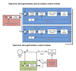
One of the main challenging aspects of microgrids is their internal controls. Different control systems within the microgrid system take care of the voltage, sharing of load current between the power converters, as well as charging and discharging of energy storage systems like batteries and supercapacitors. These control systems are generally organized in a hierarchical control system consisting of three levels: primary control local to each converter in the microgrid, including current and voltage control based on what’s called a droop control system; secondary control which restores deviations caused by the primary control, and tertiary control which handles the power flow between the microgrid and any outside electrical distribution system.
Droop control is basically a way of equalizing current sharing among converters—it is analogous to reactive power sharing in an ac grid. Conventional droop control works by adding virtual resistance in various lines to equalize the currents. Droop control also prevents circulating currents between the power converters.
However, droop control creates voltage deviations in the microgrid, which creates a need for a voltage restoration controller within the secondary control. This voltage restoration controller is common to all power converters within the dc microgrid. It corrects the dc microgrid bus voltage to the desired value. In addition, another layer of control called tertiary control takes care of the flow of power inwards and outwards between the microgrid and the electrical grid.
Today, all these control algorithms are applied using microcontrollers, and the various variables (like output current and output voltage) are sampled using ADCs. Generally, a microcontroller local to each power converter handles the primary control. Secondary control is taken care of by another microcontroller. It executes a secondary control algorithm which is common to all power converters within the dc microgrid.
A common microcontroller also generally takes care of tertiary control by monitoring and controlling the power flow or current within, in, and out of the microgrid. Other higher-level control systems like Energy Management Systems (EMSs) are then employed to decide on any need to connect or disconnect to the main grid. These algorithms are generally based on the energy available in the microgrid.
Storage systems made up of battery banks integrated in the microgrid also have their higher-level control algorithms like Battery Management Systems (BMSs) which decide when to charge and when to utilize the batteries. The power converter is controlled by the BMS, connecting the battery bank to the dc bus.
Primary control
The main or primary control system for a dc/dc converter generally consists of nested current and voltage loops. When the converters are connected in parallel within a dc microgrid, droop control handles load sharing among the converters. The inner current loop controls the inductor current, while the outer voltage loop controls the converter output voltage. The inner current control loop must be faster than the outer voltage control loop to minimize interaction between the two loops and thus prevent instability. Proportional Integral (PI) controllers control the inductor current and output voltage. The current and voltage PI controllers, Ci(s) and Cv(s), are of the form C(s) = Kp +(KI/s) where KP is the proportional gain term and KI is the integral gain term.

The PI controllers are designed to produce the desired response and bandwidth of the control loop. These controllers make use of the transfer functions as shown in the nearby block diagram (Figure 3), where Tmod is the transfer function representing the pulse width modulation stage, Gid(s) is the transfer function of the relationship between the duty cycle and the inductor current, and Gvi(s) is the transfer function of the relationship between the inductor current and the output voltage. These transfer functions are based on the type of power converter in use (Buck, Boost, etc).
In many of the dc microgrid operating modes, droop control handles load sharing between parallel-connected energy source converters by adjusting converter voltage and current control loop references.. As mentioned before, this method prevents circulating currents among the parallel-connected converters which would result if there are any differences in the converter output voltages.
There are two main types of droop control methods: the impedance droop method, which is also referred to as V-I droop; and the admittance droop method, which is also referred to as I-V droop.

The V-I method can be considered the traditional droop control method. V-I droop is applied by inserting an additional loop containing a virtual resistance Rdroop. The product of the output current and the droop virtual resistance is subtracted from the voltage reference. This causes a load-dependent deviation in the output voltage of the converter and thus a load sharing behaviior between the parallel-connected converters. The value of Rdroop is basically the slope of the V-I curve: Rdroop=(Vref-Vmin)/Imax = ɛv /io_max where Vmin is the converter’s minimum permitted output voltage, Vref is the no-load output voltage reference, and Imax is the converter maximum current. io_max is the maximum output current and εv is the maximum permissible voltage deviation calculated by εv = Vref − Vmin.
Therefore, the converter output voltage vo can be expressed as vo =Vref − Rdroopio where io is the output current. In the case of a Buck converter where the average inductor current and output current are about equal, the inductor current iL can be used instead of io in the control loop.
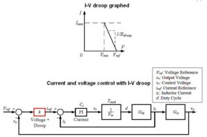
Now consider the I-V or Admittance Droop control method. Here the voltage PI controller is replaced with a multiplier term, thus this is strictly a proportional-type controller. The multiplier is denoted by a constant value k, which effectively is the inverse of the droop virtual resistance Rdroop, k = 1/Rdroop . The multiplier term k is multiplied to the difference between the voltage reference and the actual output voltage to obtain the current reference for the current PI controller.
The plant transfer functions that are used to design the current PI controller and used with the multiplier term k are the same transfer functions as discussed earlier; Tmod is the transfer function representing the pulse width modulation stage. Gid(s) is the transfer function of the relationship between the duty cycle and the inductor current. Gvi(s) is the transfer function of the relationship between the inductor current and the output voltage.

It is interesting to consider the simulation of two Buck converters sharing a resistive load, Fig. 6 and 7. The two converters were controlled by nested current and voltage PI controllers with a V-I droop loop. The droop resistance Rd was set to 0.092 Ω for both converters to share loads equally. The reference voltage for the voltage loop was 48 V.
Initially only one converter was switched on, supplying a resistive load of 0.92 Ω (52.08 A at 48 V for 2.5 kW). At t = 3 sec, the second converter was connected in parallel with the first and started sharing the resistive load. When the two converters operated in parallel, their respective droop loops adjusted each converter output voltage to share the load current. There was a change in load at t = 25 sec, decreasing the total resistive load to 0.8 Ω and causing a 15.2% change in load current. At t = 40 sec the resistive load changed back to 0.92 Ω.
Figure 7 shows the output current from each converter (Io1 and Io2) and the total output/load current (Io), during start-up, the load sharing, and the load change while Fig. 8 shows the output voltage (Vo) during the same process. It took about 13 seconds for load sharing between the two converters to reach steady state. The total output voltage rose from about 43.64 to 45.71 V, thus boosting the total output current from about 47.35 to 49.6 A. Increasing the droop resistance would make for faster sharing but at the expense of a bigger deviation in output voltage. Thus there’s a compromise between sharing speed and output voltage regulation.
Secondary control
As mentioned before, though droop control permits the sharing of a common load among paralleled converters, it also causes an output voltage deviation that depends on the load. The voltage deviation problem can be solved with a secondary controller. This controller forms an outer control loop common to all the converters/sources in the microgrid. This control loop compares the microgrid voltage with the desired voltage, and the PI compensator of the loop generates the voltage restoration needed for the primary control loops of each converter in the microgrid.

The demanded value of the voltage restoration loop (Vmgref in figure 9) is set to the desired dc microgrid voltage. The actual dc-bus microgrid voltage vmg is measured and fed back to this loop. This lets the controller generate the required restoration voltage vres. The value of vres is restricted to prevent it from exceeding the maximum allowed voltage deviation. With the V-I droop method, the equation for the output voltage vo is modified to include the restoration voltage: vo =Vref +vres − Rdroopio.
Tertiary control manages power flow between a microgrid and external grid networks. This power flow management helps reduce power losses and optimizes power generation sources. This level of control can have various complexities that range from managing the connection of the microgrid to the grid, according to the load requirements and power availability within the microgrid, to complete management of the various power sources to maximize their output within the microgrid.
Research on dc microgrids
Many research groups in universities are interested in dc microgrid research. For example, the Dept. of Industrial Electrical Power Conversion at the University of Malta has researched microgrids, both ac and dc systems. There an experimental laboratory-based 5-kW dc microgrid was set up for studies on energy control algorithms and converter prototypes. The experimental dc microgrid was designed and built in-house and consists of three power converters; two Buck converters used to emulate energy sources and one bidirectional converter connecting a battery storage system.
Each converter prototype was designed to be open for further research development. The research has produced an innovative control system offering good performance in load current sharing within a dc microgrid. A battery management system was also designed to control energy flow in the battery storage unit. The plan is to keep developing the dc microgrid setup and the power converter prototypes, as well as the control system. Companies and entities with interests in research collaborations and/or sponsorships are welcome, and can contact Dr Daniel Zammit using email daniel.zammit@um.edu.mt.
The research work in the area of dc microgrid at the Faculty of Engineering was carried out as a project by engineer Daniel Zammit as part of his doctorate studies, under the guidance of Prof. Cyril Spiteri Staines, Prof. Maurice Apap, and Dr. Alexander Micallef.
References
J. M. Guerrero, J. C. Vasquez, J. Matas, L. G. de Vicuna, and M. Castilla, “Hierarchical Control of Droop-Controlled AC and DC Microgrids – A General Approach Toward Standardization,” IEEE Transactions on Industrial Electronics, vol. Vol. 58, January 2011.
T. Dragicevic, X. Lu, J. C. Vasquez, and J. M. Guerrero, “DC Microgrids – Part I: A Review of Control Strategies and Stabilization Techniques”, IEEE Transactions on Power Electronics, Vol. 31, Issue 7, pp. 4876 – 4891, July 2016.
T. Dragicevic, X. Lu, J. C. Vasquez, and J. M. Guerrero, “DC Microgrids – Part II: A Review of Power Architectures, Applications and Standardization Issues”, IEEE Transactions on Power Electronics, Vol. 31, Issue 5, pp. 3528 – 3549, May 2016.
F. Gao, Y. Gu, S. Bozhko, G. Asher, and Pat Wheeler, “Analysis of Droop Control Methods in DC Microgrids”, IEEE 2014 16th European Conference on Power Electronics and Applications (EPE’14-ECCE Europe), 26-28 August 2014, Lappeenranta, Finland.
Y. Han, X. Ning, P. Yang, and L. Xu, “Review of Power Sharing, Voltage Restoration and Stabilization Techniques in Hierarchical Controlled DC Microgrids”, IEEE Access, Vol. 7, pp. 149202 – 149223, 11 October 2019.
K. M. Bhargavi, N. S. Jayalakshmi, D. N. Gaonkar, A. Shrivastava, and V. K. Jadoun, “A Comprehensive Review on Control Techniques for Power Management of Isolated DC Microgrid System Operation”, IEEE Access, Vol. 9, pp. 32196 – 32228, 19 February 2021.
S. Ali, Z. Zheng, M. Aillerie, J. P. Sawicki, M. C. Péra, and D. Hissel, “A Review of DC Microgrid Energy Management Systems Dedicated to Residential Applications”, Energies, Vol. 14, Issue 14, 17 July 2021.
D. Zammit, C. S. Staines, M. Apap, A. Micallef, ‘Alternative Droop Control Method using a Modified Lag Compensator for Paralleled Converters in DC Microgrids’, IEEE 6th International Conference on Control, Decision and Information Technologies (CoDIT’19), Paris, France, 23-26 April 2019.
D. Zammit, C. S. Staines, M. Apap, A. Micallef, ‘Paralleling Converters in DC Microgrids with Modified Lag I-V Droop Control and Voltage Restoration’, ELECTRIMACS 2019, Salerno, Italy, 21-23 May 2019.
D. Zammit, C. S. Staines, M. Apap, A. Micallef, ‘Paralleling Converters in DC Microgrids with Modified Lag I-V Droop Control and Voltage Restoration’, Chapter in book ELECTRIMACS 2019 – Selected Papers – Volume 2, Springer, 2020.
D. Zammit, M. Apap, A. Micallef, C. S. Staines, ‘A Battery Management System Applied to a Bidirectional Converter for a DC Microgrid Application’, publication in process.






Leave a Reply