
It pays to know about the ASIL B compliance measures needed for automotive subsystems.
Szukang Hsien, Automotive Business Unit, Maxim Integrated
TAKE the wheel of a new car today and you’ll be greeted with the bright glow of screens filled with useful data: how fast you’re going, what’s playing on the radio, a playlist of your songs, a phone book of your contacts, a map highlighting your current route, the fuel efficiency of your vehicle, whether there’s another car in your blind spot. Vehicle displays now show critical information like speed and blind spot views, but they also must be functionally safe.
Much like television screens, the displays inside cars are getting bigger and sharper. Analysts project strong growth in the greater-than eight-inch display market, with 12.3-in. displays gaining more traction for fully digital instrument clusters. By 2023, 37-in. in-vehicle screens could be common. In the coming years, resolutions of 4K (on the order of 4,000 horizontal pixels) and eventually 8K will be the norm.
Future automotive displays will boast capabilities like local dimming, which improves the contrast ratio to make colors more crisp and vivid. For instance, a black screen would be truly black, making an instrument cluster easier to read. There will also be more displays inside each car; in fact, we can already find up to 10 displays in a modern vehicle: the instrument cluster, the center information display (CID) (1-2), smart back mirror, side mirror replacement (2), heads-up display (HUD), rear-seat mount on the head support (2), and rear-seat mount on the roof.
Highlighting the infusion of display technology in cars, analysis from the market research firm IHS Markit points out that cameras and displays are increasingly serving as replacements for traditional side mirrors, improving fuel efficiency and safety. “Aerodynamic improvements and enhanced visibility are the primary reasons behind emerging mirror replacement applications, while designers will welcome newfound freedom after having explored novel exterior mirrors in concept vehicles for decades. Now that the regulatory environment is taking shape to support this concept, production applications will soon follow,” says IHS Markit. The firm projects that by 2025, nearly half a million side-view camera display systems will replace side mirrors each year in new vehicles.
These automotive displays are providing safety-critical information via advanced driver assistance systems (ADAS), so they must comply with functional safety standards. ISO 26262 is an international standard for functional safety of automotive electronic/electrical systems. A key part of the standard is the Automotive Safety Integrity Level (ASIL), which classifies the inherent safety risk in an automotive system.
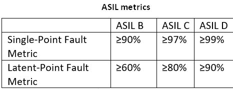 There are four ASIL levels, with ASIL D requiring the most safety-critical process and testing, based on severity (of injuries), exposure (probability), and controllability. Typical automotive systems requiring ASIL D compliance include windshield wipers, electric power steering, side-view cameras (mirror replacements), airbag deployment, braking, and engine management.
Automotive displays typically require ASIL B compliance. Within the instrument cluster display are various blocks that should meet functional safety standards. As examples, consider how two of them, thin film transistor (TFT) bias for power management and the light-emitting diode (LED) backlighting driver, can be designed for ASIL B compliance.


TFT bias typically consists of these AVDD and NAVDD voltages for the TFT source driver, VGON and VGOFF voltages for the TFT gate driver and, in some cases, VCOM voltage for the liquid-crystal display (LCD) backplane. I2C and a fault pin are used to communicate with the host microcontroller unit (MCU).
To achieve ASIL B compliance, the TFT bias block should ideally have the following features: I2C (the data signal and the clock signal) and the fault pin to perform setting adjustments and diagnostics on each rail; undervoltage and overvoltage on each rail; internal resistors with fixed or adjustable voltage through I2C (external resistors mean more points of failure, so designers typically avoid them); redundant reference; and open enable, which provides additional redundancy. When the enable is open, the chip will look at another pin to determine whether it is on or off.
There are three TFT bias fault scenarios to be aware of: VCOM voltage goes out of range; VGON voltage is in an overvoltage situation; and fail-safe operation with open enable pin
In the first two scenarios involving VCOM and VGON voltages, the fault pin will alert the MCU of the scenario. The MCU will then read the register to validate the situation and use I2C to adjust the voltages accordingly. In the last scenario, when the enable pin is open while FEN is still high, the output voltages will fall back to the default settings. The MCU can adjust the voltage via I2C.
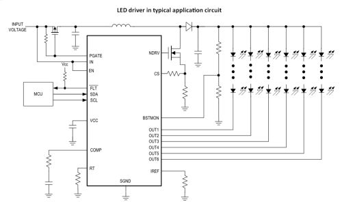
Now, consider the LED backlighting driver. Here, the input typically connects directly to the car battery, which has voltage protection when the output is short. The output can either be a boost or single-ended primary-inductor converter (SEPIC), depending on the number of LEDs per string. I2C and a fault pin are needed to communicate with the MCU.
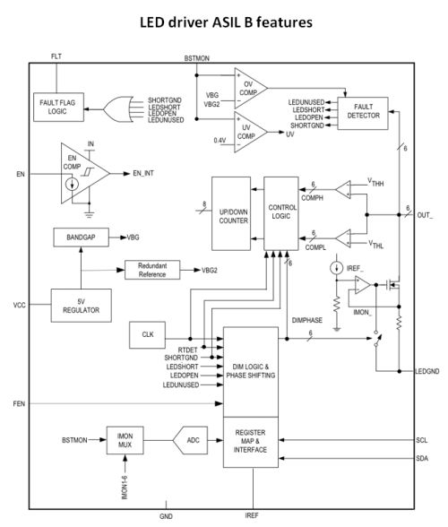
For ASIL B compliance, the LED driver would need these features: I2C (the data signal and the clock signal) and fault pin to perform setting adjustments and diagnostics on each rail; open or short LED per-string detection; output voltage measurement; LED current measurement per string; internal resistors with fixed output or adjustable output through I2C; open enable; and a redundant reference to monitor the output.
As with the TFT bias application, there are also fault scenarios to address with LED drivers:
If string 1 has an LED open. In this case, the fault pin will alert the MCU, and the MCU will read the l2C register to know which LED string has an open. The MCU will then pump more current to the other strings to reach the same brightness.
If string 2 has an LED short. As with the previous scenario, the fault pin will alert the MCU, and the MCU will read the I2C register to know which LED string has the short. To save power, the LED driver will shut down the string with the short. The MCU will then pump more current to the other strings to produce the same brightness.
If boost output voltage is low. The fault pin again alerts the MCU, and the MCU reads the I2C register to know that the boost voltage is low. Usually, the out capacitor is short to ground, or the LED is short to ground. A front protection device, such as PGATE, will be open. In this scenario, only important messages like speed or engine temperature will be displayed on the dashboard.
Fail-safe operation with open enable pin. When the enable pin is open while FEN is still high, the LED driver current falls back to the default settings. The MCU can adjust the current via I2C.
Many TFT bias ICs don’t have a communication mechanism. But an example of one that does is made by Maxim. Among the TFT bias products, for instance, is the MAX20067 TFT-LCD bias IC with VCOM buffer, level shifter, and I2C interface. This PMIC provides the industry’s first integrated power solution for TFT-LCD with synchronous boost, gate shading, and I2C. Its I2C interface offers settings control as well as diagnostics and monitoring. It also has spread-spectrum modulation in the AVDD boost converters, which reduces peak interference and optimizes electromagnetic interference (EMI) performance.
Among the backlighting products are the MAX20446 six-channel, I2C LED driver with high-voltage dc-dc controller and battery disconnect. The chip’s integrated current-mode switching controller drives a dc-dc converter that provides the voltage needed for multiple strings of high brightness (HB) LEDs. I2C offers settings control as well as diagnostics and monitoring to support ASIL B requirements. Spread spectrum with phase shifting and hybrid dimming enhance EMI performance. The IC also offers a high dimming ratio to handle bright sunlight as well as pitch-dark environments.
All in all, needle-based speedometers, fuel gauges, and the like are quickly becoming things of the past as vehicle dashboards go digital. As the auto industry moves toward Level 5 fully autonomous vehicles, functional safety of key vehicle components, such as these digital displays, will be essential. For the underlying display technologies, functional safety is marked by compliance with the ASIL B standard. Automotive-grade ICs that are designed to meet ASIL B criteria can help streamline the design cycle for reliable, high-performing display applications designed to support driver, passenger, and pedestrian safety.
Which MCU would you recommend for ASILB?