
Sometimes you need to make a “floating” measurement of a current or voltage. By “floating” I mean that you want to measure a voltage across something (or current through something) where neither end of the voltage are ground (0V). While one input being referenced to a supply rail other than 0V isn’t strictly speaking “floating,” anything that isn’t ground referenced needs special care.
So, it is a differential measurement which should be easy enough. It is, provided you take care of some of the possible pitfalls. You could use an instrumentation amplifier, but that would be overkill. For some specialist applications, you will find specific chips such as high side current amplifiers, e.g., the LT6107 from Linear Technology. However, here I am interested in more straightforward, opamp-based circuits.
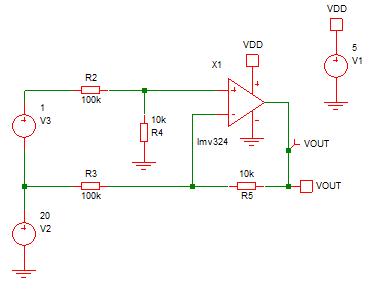
The circuit above shows a typical problem. Say you want to measure V3, but it has an offset (V2). In this case, I have made it look harder by making the offset, V20, much higher than the supply voltage of the opamp, which is 5V. However, that is not a big problem – I have made the gain of the circuit low. So, while V2 is 20V, the inverting opamp input is only seeing around 1.82V – well within the operating range of the opamp. With the values shown you could work with over 45V of common mode voltage depending on the range of differential voltage, you want to measure.
This circuit shows some of the problems people encounter when making floating measurement circuits:
1. exceeding the input voltage range of the opamp,
2. forgetting the reference voltage of the differential amplifier,
3. expecting too much output voltage range from the opamp,
4. neglecting to consider differential input voltages of either polarity (where that is a design requirement).
If you look at the output of the circuit when you sweep V3, you will see some of the problems.
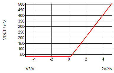
The first problem is that the output voltage will only respond to positive voltages of V3, i.e., the non-inverting opamp input above the inverting input. You should expect this when everything is ground-referenced and the negative opamp supply is ground. The opamp output cannot go below its negative supply voltage (0V in this case).
The other problem is that the opamp output doesn’t quite reach zero and the output doesn’t start to move until V3 is around 200mV. Again, you should expect this — rail-to-rail opamps often don’t quite make it down to ground unless there is a low-value load resistor to ground.
A slight change to the circuit can make it work for both positive and negative differential input voltages. You could also add some gain, but only if you keep the input voltage within the opamp operating input voltage range. The opamp shown is not rail-to-rail input — the input voltage can include the negative rail but not the positive rail. A common requirement is to measure the current into or out of a battery (i.e., charging and discharging). The circuit below will do that.

By changing the resistor values, we now have a gain of 10 so 100mV of input voltage will produce 1V of output voltage. It will be offset though, due to R4 going to a new voltage V4 rather than ground. So the differential amplifier reference voltage has changed. V4 must be a low impedance voltage source, so it doesn’t vary with the input voltage and affect the gain. If you do not need high accuracy and can live with the same accuracy as Vdd, then you can replace V4 and R4 with 200k resistors to both Vdd and ground. This has the same effect as 100k to mid-rail. Alternatively, if you are connecting the opamp output to a differential ADC (analog to digital converter), you could connect V4 to one of the ADC inputs.
The output from the circuit is shown below.

Zero volts of differential input will result in 2.5V of output due to V4. That means that you can measure either polarity of differential input voltage. V4 doesn’t have to be 2.5V or mid-rail – it all depends on what you are trying to measure.
In this case, I have changed the opamp to the OPA340 from the LMV324. The OPA340 is a lot better at getting close to the supply rails. If you only lightly load the opamp output, you can get within 1mV of the supply rails. Similarly, the input voltage range extends beyond the voltage rails by 0.3V giving a bit more flexibility in the design.
The differential voltage V3 could be derived from a small series resistor in your power supply to measure the charge/discharge current of a circuit. In that case, you would want the resistor value to be small so the voltage drop across it is small. And a gain higher than 10x might be appropriate. You should also make sure that the resistor values sensing the voltage across the current sense resistor are large enough not to affect the current sense resistor. If you have a sense resistor of a few ohms and use resistors of at least 10k ohms to connect to the opamp, then they will not have a significant impact on accuracy. If you use a high closed loop amplifier gain, you need to work out the effects of the opamp input offset which will degrade accuracy.
Leave a Reply