
By Bill Luo (Luo Zhizheng), Sr FAE, ACEINNA Transducer Systems and Jason Zhang (Zhang Liang), AE Director, Shenzhen Advantaged Power Limited
There is a lot of attention being paid to advanced power systems. Energy efficiency has become a critical capability in today’s world, due to pressures from every sector of the market. To achieve substantial benefits, every application solution needs to run at the highest efficiency it is capable of achieving. More efficient systems have reduced thermal issues, improved operating costs, and other cascading benefits from more optimized functionality.
For example, not only does reducing the thermal load on the system save money and reduce the need for cooling, but the cascading benefits include reduced thermal shock and therefore longer MTBF, It also relaxes the packaging and insulation requirements, which increases footprint and form factor flexibility, reduced bill of materials, and on, for every subsystem. This enhances the functionality, reliability, durability, and operational lifetime of the product itself.
When it comes to advanced systems like robotics, wearables, green energy, and the smart grid, the amount of power being generated, transferred, and converted at multiple stages is substantial. Not only must every player in the game operate as efficiently as possible, they must do so. Creating efficient power solutions is a critical aspect of every design today, no matter the size and power level.
Providing advanced functionality needs lots of power, and it is behind almost everything in our modern society. This demand for power is going up exponentially with the growing number of devices being turned on every day, and efficiency is the only way to mitigate that massive demand.
Regardless of the core technology, electronics need electricity to work, and nothing happens unless you have energy. Artificial Intelligence, Cloud-based IoT, next-gen RF technologies, self-driving EVs, and other advanced solutions have significantly increased the overall global electrical power demand. This drives power engineers and architects to extend existing power technology boundaries to achieve higher system efficiencies, faster response times, and more robust and reliable solutions.
Advanced topology innovations and new power semiconductor advances have also provided solutions to address power electronics efficiency. For example, fast-switching wide-bandgap Silicon Carbide (SiC) or Gallium Nitride (GaN) semiconductors are currently revolutionizing the industry. In addition, isolated single-chip current sensors in bridgeless Power Factor Correction (PFC) and DC-DC converters are also improving efficiency and thermal management.
This complementary mix of solutions must be well integrated in order to address the application in the most cost-effective manner. An important aspect of power design is just making sure you have the right pieces to build your solution.
Creating an efficient Totem-Pole PFC for a power system
A Totem-Pole PFC can be considered as a synchronous-rectifier boost DC-DC converter. However, the problem is the reverse-recovery charge of the MOSFET body-diode that occurs when the converter works in CCM (Continuous Conduction Mode) condition. This means that the Totem Pole PFC can only work in DCM (Discontinuous Conduction Mode) or BCM (Boundary Conduction Mode) mode with traditional Si-MOSFET. But both have challenges.
A DCM PFC can only support low power applications. When using a BCM PFC, the operation frequency varies widely. In addition, the peak current will be 2 times of a CCM PFC, which increases the difficulty of EMI filter design and efficiency optimization. With the availability of fast-switching wide-bandgap SiC- and GaN-based power switches, Totem-Pole PFC designs can now operate in CCM mode to provide higher efficiency and power.
One of the first steps in your power design should be your power switch selection. To choose a suitable MOSFET, we need to calculate the voltage, current and power loss in the device. In our example, in our test application, to minimize switching power loss, we chose the Wolfspeed 4-Pin SiC-MOSFET C3M0065090K, a 900V, 65mohm device for the high-frequency switches. The device has a fast intrinsic diode with low reverse recovery (Orr) and has very low output capacitance (60pF).
For the low-frequency switch we chose an Si-MOSFET, whose power loss is mainly due to Rds(on). So, we selected the low Rds(on) MOSFET IXFH80N65X2 because of its high level of efficiency.
The input inductor is designed to keep the current ripple under 30% of the maximum peak input current, where the maximum peak input current occurs at low line and at full load. For this design, the minimum inductance value is 200μH. The output capacitance is determined by two constraints, load hold-up time and output voltage ripple regulation. In this design, the hold-up time is set to be 10ms and the output voltage peak to peak ripple is set to be 30 V. So, we choose the HP 450V560μF (30×50) capacitor, used in parallel to meet the requirements.
Totem Pole PFC control block diagrams and circuit simulation
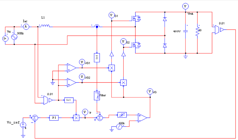
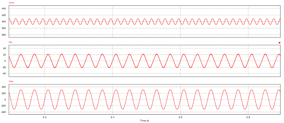
The Totem Pole PFC control block diagram is shown in Figure 1 and the related application control circuit is shown in Figure 2. The simulation results in Figure 3 shows that the PFC circuit can work well.
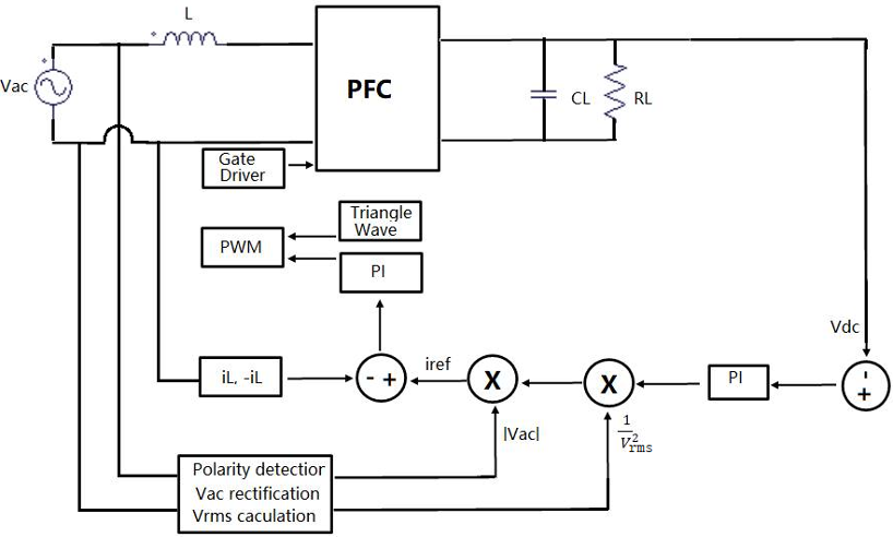
- Reference current Iref = K(Vdc-Vdc_ref)*|Vac|*1/V²rms
- K is depends on Proportional-Integral time constant
- (Vdc-Vdc_ref) is the output voltage error
- |Vac| is the follower factor between the voltage and current
- 1/V²rms is the power limitation factor
- Input loop current IL must be monitored cycle by cycle accurately and needs control loop pole placement for stability.
- The current error Δi = (k1*IL+k2*∫IL)-Iref, it is a key parameter for the average current mode control. K1 is linear coefficient and k2 is integral coefficient.
- The PWM signal is generated from the comparator which compares the current error Δi with a triangular wave.
Digital control and algorithms
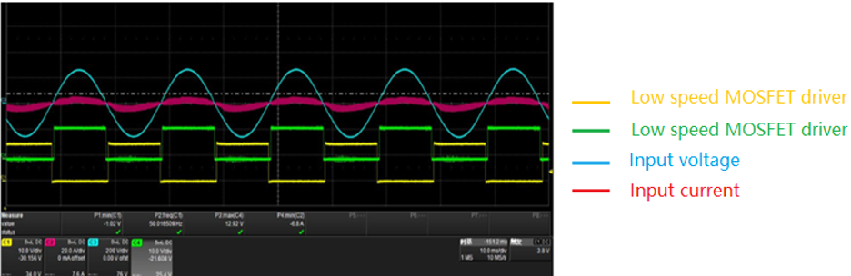
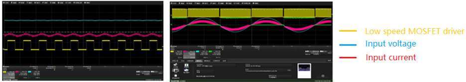
Another challenge in Totem Pole PFC design is that the AC line zero-crossing point may create shoot-through issues, requiring knowledge of when the positive cycle transitions to negative cycle. In order to do this, the AC line voltage is sensed and sent to the ADC of the MCU. A Phase-Locked Loop (PLL) algorithm based on second-order generalized integrators (SOGI) is adopted, and the calculation result can be used to generate the low-frequency driver.
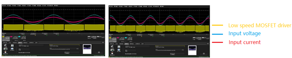
It is easy to insert the dead time in the low-frequency driver pulses. The test result is shown in Figure 4. The Green and Yellow signals are the driver signals of low-frequency Si-MOSFET based on the PLL result.
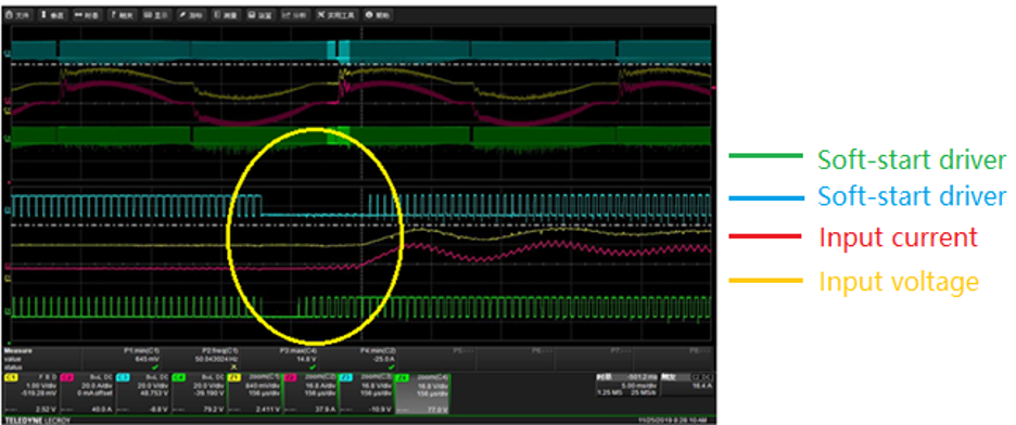
Soft-start during Zero Crossing
The line current in a single-phase PFC topology distorts at the zero-crossing point of the input AC voltage. This is because of the characteristic of the general proportional integral (PI) current controller, and this distortion degrades the line current quality. This in turn impacts things such as the total harmonic distortion (THD) and the power factor (PFC) of the circuit.
There are two main reasons for this distortion. The first is the dynamic response of the PI controller, as its dynamic response is considerably slow. The line current is distorted because the error of the PI controller is considerably large at the zero-crossing point. The second reason for this distortion is the PFC converter operates in the DCM, near the zero-crossing point of the input AC voltage.
The line current cannot follow the reference current, which results in line-current distortion. To deal with this issue, the soft-start and dedicated time sequence of the high-frequency SiC-MOSFET during zero crossing is adopted in the firmware. With such a design, the current has very little zero-crossing distortion, and THD is 2.8% in full load condition.
Current and voltage control loop
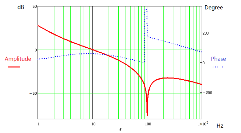
In our example we used an MCU from Spintrol to realize the PFC control, integrating the algorithm of SOGI PLL, Current loop PI Controller, Voltage loop PI controller, and software /TZ protection. A 60kHz interrupt is set in the firmware and PI control loop, and in PFC applications, it needs a fast-current loop to keep the controlled input current following the input voltage. We choose the bandwidth of the current loop to be 3kHz and phase margin to be 60 degrees, according to the Nyquist stability condition.
In the practical application, to minimize linearization and accuracy limitations in small signal modeling, the cutoff frequency of the control loop is set at around 0.03~0.25 times the carrier (switching) frequency. With dedicated parameters, the final current loop is shown in Figure 5. The current is sampled at the average value and it is equivalent to the middle point in each 60kHz switching cycle. A 10kHz interrupt is set in the firmware and the PI control loop is adopted for the voltage loop.
Because the PFC output voltage has twice the line frequency voltage ripple, which results in a third harmonic current, the voltage loop’s bandwidth needs to be kept low enough to minimize the third harmonic. The bandwidth of the voltage loop is set to 10Hz and 60-degree phase margin. The voltage loop must be cut off in low frequency in order to make input current a sine wave. Another 100Hz notch is inserted in the voltage loop to further decrease the third harmonic current.
With chosen parameters, the final current loop and voltage loop gain and phase margins are shown in Figure 5 and Figure 6 respectively.

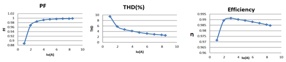
Test results
Based on the design above, a 3.3KW Totem Pole PFC demo board is built, and the test results and waveforms are shown in the following pictures. Features of the design include 99.1% peak efficiency and 98.5% full load efficiency, with a THD of 2.8% achieved at full load.
From the test results, we can see that the selected SiC-MOSFET and high bandwidth current sensor worked well in this application for Totem Pole PFC control and protection with low cost MCU. Please refer from Figure 7 to Figure 9.
Authors
Bill Luo (Luo Zhizheng), Sr FAE, ACEINNA Transducer Systems Co., Ltd – Graduated with a bachelor degree from North University of China. He has worked for three years doing R&D at Shenzhen Gold Power Limited, seven years at Shenzhen Onstone Limited as a FAE manager and two years in the Arrow Group as Sr FAE/FAE manager. He is highly experienced with MOSFETS, IGBT, Sic, GaN devices applications in power field and is very knowledgeable in Air-conditioner, Inverter, Solar Inverter and EV Charging Station applications.
Jason Zhang (Zhang Liang), AE Director, Shenzhen Advantage Power Limited – Zhang Liang majored in power electronics and has bachelor (2002) and master (2005) degrees from Nanjing university of Aeronautics and Astronautics at 2002 and 2005 respectively. He has over three years work experience as power engineer at Astec, Emerson Network Power and eight years senior application engineer at Texas Instruments. Since 2015, he has worked at Shenzhen Advantage Power as Application Leader and has focused on the applications of third generation semiconductor and AC-DC/DC-DC power systems.


Thanks. Nice research on Power factor controllers.