• Skip to primary navigation
  • Skip to main content
  • Skip to primary sidebar
  • Skip to footer
  • Subscribe
  • Advertise

Power Electronic Tips

Power Electronic News, Editorial, Video and Resources

  • Products
    • Power Supplies
    • AC-DC
    • DC-DC
    • Battery Management
    • Capacitors
    • Magnetics
    • MOSFETS
    • Power Management
    • RF Power
    • Resistors
    • Transformers
    • Transistors
  • Applications
    • 5G
    • AI
    • Automotive
    • EV Engineering
    • LED Lighting
    • Industrial
    • IoT
    • Wireless
  • Learn
    • eBooks / Tech Tips
    • EE Training Days
    • FAQ
    • Learning Center
    • Tech Toolboxes
    • Webinars & Digital Events
  • Resources
    • Design Guide Library
    • Digital Issues
    • Engineering Diversity & Inclusion
    • LEAP Awards
    • Podcasts
    • White Papers
    • Design Fast
  • Video
    • EE Videos & Interviews
    • Teardown Videos
  • EE Forums
    • EDABoard.com
    • Electro-Tech-Online.com
  • Engineeering Training Days
  • Newsetter Subscription

How trimming affects thick-film resistor performance

February 16, 2022 By Kory Schroeder

Ordinary thick-film resistors can display varying qualities depending on how the manufacturer elected to trim the device.
It pays to know what to look out for.

Kory Schroeder, Stackpole Electronics Inc.
Surface-mount thick-film chip resistors are the predominant type of resistor in electronic circuits today. This technology is inexpensive; thick-film resistors are produced by screen-printing a special paste (a mixture of glass and metal oxides) on to a ceramic substrate. Depending on the size of the chip, hundreds or thousands of parts may be processed simultaneously. The screen printing process generally yields resistors within 5% to 20% of the required value, so manufacturers calibration-trim the resistors by laser to get the right value without slowing resistor production.

There are different laser trim designs and shapes which present different manufacturing challenges and that yield different strengths and weaknesses.

The process of laser trimming thick-film resistors involves pulsing a round laser beam into the cured thick-film material. The laser light vaporizes the material under and around the beam. Removal of resistor material slightly raises the resistance value. Subsequent pulses remove more material and further raise the value of the resistance.

plunge and double cut
Top, the plunge cut is the most economical laser trim type though overall tolerance accuracy can be less than the other methods. This method is often recommended for dc applications. Below, double cut trim speed can be greater than for a single cut because precision comes from the second cut, which sits in a less sensitive trim area than the first. The second trim is generally kept to within 50 to 80% of the first trim length for the best adjustment results.

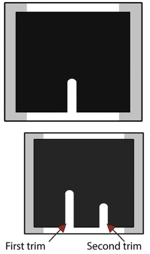
The simplest and most obvious trim shape is the single plunge or straight cut. Of all the trim shapes it can be made the fastest but is also less precise than some other trim designs. The single-plunge trim is challenging for high precision because the further the cut into the element, the greater the effect. This trim type isn’t practical if the initial element value is far below the desired value because it will be difficult to adjust the resistance value without overshoot. However, a single-plunge trim is economical when the initial resistance is close to the final resistance value—trimming doesn’t take long and it is relatively easy to control the resistance value. But the trim speed for single-plunge trim tends to be somewhat slower than for other types though overall trim time is less.

Pulse-handling resistors should have little if any trimming. Current crowding effects—peaks in the current density–arise in the area around the trim, and that is the failure point for thick-film resistors under pulse conditions. So pulse-handling resistors are generally printed to close to their desired resistance. The single plunge is a effective trim shape for these types of resistors, but it is often too imprecise for general purpose and commodity chip resistors.

The double-plunge cut provides much more precision than single-plunge cuts. The first cut brings the resistance value close to the desired final value. The second cut is in an area with less current flow, so it changes the resistance much less, allowing for precise resistance control. The second trim length is kept between 50% to 80% of the length of the first cut to ensure stable electrical performance and continuous power handling. The precision for this trim shape depends only on the second cut, so the machine trim speed can be faster than for the single plunge. Many thick-film resistors are trimmed in this manner, especially those with smaller elements.

L and serpentine trims
Top, an L trim typically starts at about 15 to 20% of the total resistor length away from the conductor-resistor junction to avoid junction effects and provide the maximum room for the second cut. Below, serpentine cuts are characterized by multiple trims spaced an equal distance apart. They may be used for very high resistance values or low resistance metal elements.
L trim is another common trim shape. This shape can yield a precision resistance while also providing a greater range of resistance value adjustment. The initial trim into the part stops when the resistance value begins to change rapidly. Then the laser changes direction and proceeds toward the opposite termination.

The second part of the trim allows for precision control because the current crowding arises only along the first part of the trim, so the second part causes much less change in resistance. L trimming can usually take place at the same speed as a double-plunge trim. The L trim is generally regarded as a more stable trim than single or double plunge but requires a somewhat larger resistor area for effective value calibration. Most thick-film resistors currently on the market will have either a plunge or L cut trim.

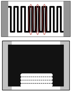
Serpentine cuts may be used to adjust resistance to a value significantly higher than the printed resistance. Trims are spaced equally apart and continue until the resistance value is reached. This trim type will have higher parasitic noise, lower overall stability, poorer pulse performance. And the resistance material must be long enough to permit adequate value adjustment. Thus serpentine cuts are most effective for high resistances where power and current handling requirements are irrelevant.

Serpentine cuts are also occasionally used for adjusting metal plate sense resistors. These resistors generally use resistive material comprised of exotic alloys such as manganese-copper or nickel-chromium-aluminum to obtain special properties such as low inductance or low thermal EMF. Even when timed with serpentine patterns, their element mass and pulse capability stays roughly the same despite the length of the trims and the substantial amount of material removed.

top hat and scan cuts
Top, top-hat trims are effective for trimming high resistance and high voltage precision film elements. Below, the scan cut offers both high accuracy and high frequency compatibility. The resistor material is removed only from the edge of the resistor body. This technique typically requires considerably more time per resistor than the other trim types.
Top hat trims—so named because the resistor material topology resembles the outline of a top hat– provide the best accuracy and stability for high voltages and high resistance values. Top hat trims require a precise serpentine resistance element and are best for larger chip sizes. The serpentine resistance pattern dramatically increases both the voltage capability and resistance value of the element. The top hat portion of the element provides a wider area for the laser trim, allowing precision value control without harming the resistor’s voltage capability. Most precision high-voltage resistor series utilize the top hat type of trim.

In scan cut trims, resistor material is typically removed from each edge of the resistor equally. Scan cuts are generally used when the adjustment range is small and high precision is required. This trim process is significantly slower than others and requires overlapping subsequent laser trim scans to ensure all material from each trim is completely removed. The best stability comes from starting and finishing scan trims in the conductors on the ends of the element. This type of trim requires materials that are compatible with this trim operation. Thus this type of trim is not commonly used because of unique material requirements and of the time and control required.

Laser trimming effects

microcracks
Microcracks arising because of the laser trimming process may extend into the resistor material causing potential drift problems. Microcracks can also cause a shift associated with the temperature coefficient of resistance (TCR).
It should be noted that the basic rule for trimming is that the trim itself should be minimized. For thick-film resistive elements, the process of laser trimming has detrimental effects which can’t be overcome. As the laser moves through the element, the material adjacent to the laser trim permanently changes. The thick-film material heats up in proportion to the distance from the laser trim. As this material cools, microcracks develop because the cured thick-film material conducts heat relatively poorly. These microcracks lead to poorer TCR (temperature coefficient of resistance), poorer lifetime stability, higher parasitic noise, and increased VCR (voltage coefficient of resistance).

VCR curves
One outcome of the trimming process can be a shift in resistance values during the resistor’s operating life and a change in resistance with voltage, particularly for high-resistance thick-film resistors.
Also at the edge of the trim a dielectric glass layer forms. The material at the edge is referred to as laser slag and has a non-uniform appearance. The dielectric glass layer helps to stabilize resistive material at the trim edges and prevents it from falling into or across the trim line.

The effect of trimming becomes evident in graphs of resistance vs. VCR and resistance change vs. operating time. Generally speaking, trimming can cause significant degradation of VCR and resistance change over the life of the part.

All in all, each trim shape has its advantages relative to the design goals of specific thick-film resistor series. Manufacturers minimize the trim length to ensure the best possible TCR, overall stability, and lowest noise.

You may also like:

  • charging
    Say goodbye to cross-country road trips
  • battery breakthrough fatigue
    Battery breakthrough fatigue
  • electrolytic caps
    Why electrolytic capacitors blow up

  • Power supply designers take a hard look at soft magnetics
  • LEDs
    LED bulbs then and now: Teardown of the EcoSmart, Feit,…

Filed Under: FAQ, Featured, Power Components, Resistors Tagged With: FAQ, stackpoleelectronics

Primary Sidebar

Featured Contributions

Robust design for Variable Frequency Drives and starters

Meeting demand for hidden wearables via Schottky rectifiers

The case for vehicle 48 V power systems

GaN reliability milestones break through the silicon ceiling

Developing power architecture to support autonomous transportation

More Featured Contributions

EE LEARNING CENTER

EE Learning Center

EE TECH TOOLBOX

“ee
Tech Toolbox: Internet of Things
Explore practical strategies for minimizing attack surfaces, managing memory efficiently, and securing firmware. Download now to ensure your IoT implementations remain secure, efficient, and future-ready.

EE ENGINEERING TRAINING DAYS

engineering
“power
EXPAND YOUR KNOWLEDGE AND STAY CONNECTED
Get the latest info on technologies, tools and strategies for EE professionals.
“bills

RSS Current EDABoard.com discussions

  • ISL8117 buck converter blowing up
  • The comparison of different Tcl script checkers
  • High Side current sensing
  • Can anyone provide a guide or tutorial for Candece simulation?
  • How to simulate power electronics converter in PSpice?

RSS Current Electro-Tech-Online.com Discussions

  • Can I make two inputs from one??
  • Why can't I breadboard this oscillator?
  • Is AI making embedded software developers more productive?
  • Cataract Lens Options?
  • Back to the old BASIC days

DesignFast

Component Selection Made Simple.

Try it Today
design fast globle

Footer

EE World Online Network

  • 5G Technology World
  • EE World Online
  • Engineers Garage
  • Analog IC Tips
  • Battery Power Tips
  • Connector Tips
  • DesignFast
  • EDA Board Forums
  • Electro Tech Online Forums
  • EV Engineering
  • Microcontroller Tips
  • Sensor Tips
  • Test and Measurement Tips

Power Electronic Tips

  • Subscribe to our newsletter
  • Advertise with us
  • Contact us
  • About us

Copyright © 2025 · WTWH Media LLC and its licensors. All rights reserved.
The material on this site may not be reproduced, distributed, transmitted, cached or otherwise used, except with the prior written permission of WTWH Media.

Privacy Policy