
It pays to understand a few important electrical parameters that can dictate the kind of applications specific power supplies can handle.
Florian Haas | Traco Power Group
A few basic factors go into the selection of low-voltage dc/dc and ac/dc power supplies for OEM use. At the risk of stating the obvious, the key objective is to bring the input voltage to a new potential. With that in mind, there are six parameters that determine most of the qualities the supply should have.
Whether the input potential is divided
The input and output voltage ranges and the output current demand
The space available for the supply
The end product and the regulations that apply to its industry or area
The environmental conditions the supply will see
The degree of reliability the supply must provide
There are a few electrical parameters pertaining to supplies that need detailed specifications. They include how to deal with supply ripple and conducted noise, the handling of inrush current, thermal considerations, and electromagnetic compatibility (EMC) constraints.
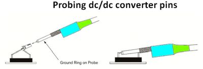
Designers typically quantify power supply requirements by measuring the power consumption of host equipment. In this regard, every measurement changes the state of the circuit; the impact of any measurement should be minimized. This philosophy implies performing a four-wire measurement even for simple tests. Measurement of current and voltage with independent test leads minimizes the impact of lead resistance on measured values.
Four-wire measurements supply current via a pair of leads called force connections. These generate a voltage drop across the impedance to be measured. A pair of voltage leads called sense connections sit immediately adjacent to the target impedance, so they do not include the voltage drop in the force leads or contacts. Because almost no current flows to the measuring instrument, the voltage drop in the sense leads is negligible.
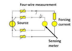
Customarily, the sense wires are the inside pair while the force wires are the outside pair. Exchanging the force and sense connections can degrade measurement accuracy because more of the lead resistance is included in the measurement. The force wires may have to carry a large current when measuring small resistances so they must be large enough to handle the anticipated level of current. The sense wires can be of a small gauge.
Dealing with inrush
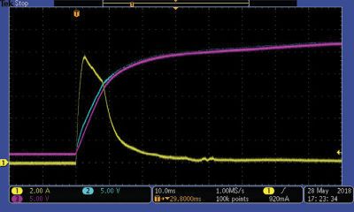
In a typical power supply, the ac current flows through a diode bridge rectifier and then flows into a filter capacitor. At power on, there is an inrush of current because the filter capacitor goes into its charging phase and acts like a momentary dead short. This inrush current can cause a number of problems.
The usual remedy is to temporarily introduce a high resistance between the input power and rectifier in the form of an inrush current limiter. An inrush current limiter often takes the form of an NTC (negative temperature coefficient) thermistor in series with the diode bridge and sometimes in series with the filter capacitors. The thermistor gives the filter capacitor time to charge without the inrush current fully hitting the load.
When energized, the NTC thermistor self-heats. The heating eventually lowers the thermistor resistance. As the resistance reaches a low value, current can pass through without degrading normal operation or power efficiency. The inrush current limiter remains at this steady-state condition, allowing the current to flow through unaffected.
It should also be said that inrush current – or specifically, the heating that can arise from inrush current – can degrade the life of electrolytic capacitors often used as input filters. The reason is that high temperatures tend to shorten the life of electrolytic capacitors. Another factor that can cause such heating is excessive ripple current.
It is common practice to measure the power supply ripple and noise on the output, though these parameters are generally spelled out in spec sheets. As a quick review, ripple voltage is the residual periodic variation of the power supply’s dc output voltage. It arises because of incomplete suppression of the alternating waveform after rectification. Ripple itself is a composite (non-sinusoidal) waveform consisting of harmonics of some fundamental frequency which can be tens of kilohertz to megahertz for switching supplies.
Several parameters describe ripple; they include the peak (usually peak-to-peak) value of the ripple voltage; the root mean square (RMS) value of the voltage which is a component of power transmitted; the ripple factor γ, the ratio of RMS value to dc voltage output; the conversion ratio (also called the rectification ratio or efficiency) η, and form-factor, the ratio of the RMS value to the average value of the output voltage.
Output ripple is undesirable for numerous reasons. It causes heating in dc circuit components because ripple current passes through parasitic elements such as the ESR of capacitors. Similarly, ripple forces designers to keep the value of parasitic elements low. Ripple voltage also forces components being powered to have higher peak voltage ratings than would otherwise be necessary. If the ripple frequency is in the audio range, it could become audible if the circuit being powered is for audio reproduction. Ditto for ripple frequencies near those by video displays. And ripple voltage that gets into digital circuits can reduce the logic threshold, as would any form of supply rail noise, making logic circuits more susceptible to incorrect outputs and corrupted data.
Usually, noise and ripple can simply be reduced with two parallel-switched capacitors, for example, a 100-nF metal film capacitor and a 10-µF electrolytic capacitor, always bearing in mind that values presented on datasheets can be influenced by other factors during end usage.
Specific industries – such as industrial equipment and medical equipment, railway/transit equipment and communications equipment – generally each have their own standards for conducted and radiated EMI. Power supplies used in those industries must follow the applicable standards. For example, CISPR (in English, International Special Committee on Radio Interference) 11 is the international product standard for EMI originating from industrial, scientific and medical equipment. CISPR 11 applies to equipment that includes wireless power transfer chargers, Wi-Fi systems, induction cooking hobs, and arc welders.
In addition, other standards bodies such as the International Electrotechnical Commission (IEC) issue EMI standards. More specifically, IEC 61000-6-3 applies to products in residential/ commercial/light-industrial applications, while IEC 61000-6-4 covers heavy-industrial uses. Certain industrial end equipment may have dedicated system-level standards that reference CISPR 11. For instance, IEC 61131-2 provides emission requirements for programmable controllers and their associated peripherals. Other system-level standards include IEC 61800-3 and IEC 61326-1, which dictate EMC requirements for adjustable-speed motor drive systems and laboratory equipment, respectively.
Virtually all CISPR-based test standards specify limits for conducted emissions measured up to 30 MHz, except for CISPR 25, where the applicable upper frequency extends to 108 MHz. EN 55015, based on CISPR 15 for lighting equipment, has a measurement range extending down to 9 kHz for some apparatus.
Use of a dc/dc converter with an internal filter doesn’t guarantee adherence to EMC values because EMC compatibility can often be affected by several components. In many cases, the output connections must include one to protective earth for safety reasons, and this can have a significant impact on EMC. Usually, the power supply manufacturer can offer advice regarding how to adhere to EMC values.
Most power supply manufacturers provide help in the form of suggestions for suitable filters on their websites. For example, suggestions can be downloaded directly from the relevant device’s page at www.tracopower.com. If you can’t find the circuit diagrams for the product you have selected, don’t hesitate to contact the manufacturer directly on the phone or by email.

Leave a Reply