
The specification process for resistors involves more than just allowing for tolerance bands. Voltage, power, and temperature ratings can interact in ways that can degrade circuit reliability.
Kory Schroeder, Stackpole Electronics, Inc.
Although not a complex component, resistors have specifications that can be confusing, misleading, and misinterpreted. When specifying performance qualities, it is important to review and understand the resistor test conditions to properly interpret and apply the results to your design. There are potentially significant differences in data presented by resistor manufacturers and those differences can significantly affect performance.
Power and voltage ratings
The power rating and voltage rating of a resistor are one common source of confusion. Simply put, the power rating is the amount of energy the resistor can dissipate in a given time at the designated ambient temperature.
Manufacturers typically list multiple voltage ratings on a datasheet, but most often the primary concern is the maximum working voltage. Maximum working voltage is the maximum amount of voltage the resistor can withstand constantly without arcing. Maximum working voltage is often expressed as Vrms.
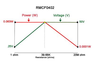
It is critical to adhere to both the power rating and the maximum working voltage rating to avoid reliability problems. For example, if a 10-Ω 0402 chip resistor was subjected to the maximum working voltage of 50 V, the resulting power through the part would be 250 W. This far exceeds the resistor power rating.
Conversely, for high resistance values, the amount of electrical energy that the 0402 resistor can withstand is determined by the working voltage rating of 50 V. If a 20-MΩ 0402 was subjected to the maximum power of 0.063 W, the voltage implied across the part would be 1,122 V, which surpasses the part’s voltage handling ability.
Only at exactly 39.68 KΩ can the 0402 resistor handle both 50 V and 0.063 W simultaneously. This value is known as the “critical resistance value”.
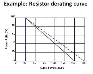
Another aspect of the power rating is the temperature at which heat dissipation is measured. Many resistors are rated at temperatures of at least 70°C. This means the part can handle the designated power rating provided the ambient temperature around the part does not exceed 70°C. However, there are some higher power resistors that are only rated for full power operation up to 25°C. These power resistors typically require some type of external heat removal to operate at full rated power.
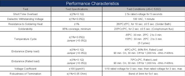
Performance specs provide information about how a resistor behaves in a test or a set of tests. Engineers will regularly use this information to compare parts from different manufacturers. For a resistor series tested to a common standard such as AEC-Q200, it is relatively easy to compare performance.
However, designers may need additional information even about AEC-compliant resistors. Some manufacturers will claim compliance with AEC (Automotive Electronics Council) testing and even provide all supporting data from AEC tests, but only carried out for small sample sizes. In some cases, these data files only show testing for 10 pieces or even fewer of each size, and in some cases, they may only show results for a single resistance value. Most AEC tests require at least 77 pieces from three distinctly different manufacturing lots in three different resistance values per size; they also spell out high, low, and critical resistance value (or as close as the nearest standard resistance value can come).
Both test conditions and the way in which test results are stated can vary widely when common test standards are not followed. These variations can lead to misleading performance statements. For example, nichrome-based thin-film resistors are susceptible to moisture corrosion. Some manufacturers will tout their nichrome elements as having superior moisture resistance, citing extremely low resistance shifts to biased humidity testing.
The load or bias on the resistor is a critical factor during testing. At full rated power, most resistors will generate enough heat to prevent moisture from condensing on the part, giving the appearance of robust moisture resistance. But in many applications, precision nichrome thin-film resistors will only see a fraction of their rated power. In these cases, the part will generate little heat, boosting the possibility of moisture condensing and collecting on the part. The resistance shift could be significantly different in the presence of a lower bias such as 10% rated power. Thus the test conditions are critical to understanding the results and ultimately to predicting resistor performance.
Another frequently asked question is how to interpret the accumulated variation or tolerance stack-ups from the different potential sources of fluctuations. Adding the maximum potential shift from all the relevant tests provides the maximum expected resistance shift or worst-case scenario.
In practice, use of worst-case figures is unnecessarily conservative for most applications. It may result in selecting a resistor with a high price tag and needlessly tight tolerance or low TCR.
It is important to remember that each performance test is independent. Some tests will typically have a positive shift in resistance, and some will typically have a negative shift in resistance. In addition, test performance typically differs from one resistor technology to the next. In most cases, the actual resistance shift seen in the circuit is much less than the sum of the individual test tolerances. It is advisable to contact the resistor manufacturer about specific stability requirements over the life of a given circuit for a resistor or series of resistors.
It is also important to understand whether the change in resistance shown in the performance specs is typical performance or the absolute maximum limit. Some manufacturers will show typical results and not state limits explicitly unless customers specifically ask. Typical results are usually two to three times better than the actual test specification. This practice creates the false impression that the part is better than other similar products when the actual performance is no better and, in some cases, worse.
In a nutshell, designs must not violate resistor power or voltage ratings; these are resistance-dependent parameters. Power ratings must be reconciled with the operating temperature. If the circuit operates at temperatures exceeding the resistor’s rated temperature, resistor power handling must be derated appropriately.
It’s also important to determine what tests are relevant to the application. Test conditions should be the same as what the resistor will actually see, and test results must be properly interpreted. The same can be said for whether test results give actual maximum possible shifts or typical performance.
Finally, the accumulated variance or worst-case scenario does not consider the distribution of the individual, independent variables. Overlooking this fact can lead to an unnecessarily constraining design and would make typical commodity resistors impractical to use. Whenever there is a question about how well a resistor suits a design, it’s best to have factory engineers examine the design details to help make the best choice.
Leave a Reply