
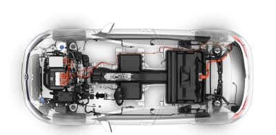
Automakers are forced to fit EV batteries into nooks and crannies in an effort to maximize driving range. The resulting convoluted layouts call for a wireless approach to managing cells.
GREG ZIMMER | Linear Technology Corp., now part of Analog Devices Inc.
Lithium-Ion batteries require considerable care if they are expected to function reliably over a long period. They cannot be operated to the extreme end of their state-of-charge (SOC). The capacity of lithium ion cells diminishes and diverges over time and usage, so every cell in a system must be managed to keep it within a constrained SOC.
It takes tens or hundreds of battery cells to provide sufficient power for a vehicle, configured in a long series generating as much as 1 kV or higher. The battery electronics must operate at this high voltage and reject common-mode voltage effects while differentially measuring and controlling each cell in these strings. The electronics must be able to communicate information from each cell in a battery stack to a central point for processing.
In addition, the operation of a high-voltage battery stack in a vehicle or other high-power applications entails tough conditions, such as the presence of significant electrical noise and wide operating temperatures. Nevertheless, the battery management electronics are expected to maximize operating range, lifetime, safety and reliability, while minimizing cost, size and weight.
Steady advances in battery cell monitoring ICs have given battery packs in automobiles high performance, longer life and reliability. The development of the wireless BMS (battery management system) promises to further improve safety and reliability of the full battery system.
In 2008, Linear Technology announced the first high performance multicell battery stack monitor, the LTC6802. Among its features, the LTC6802 measures up to 12 Li-Ion cells with 0.25% maximum total measurement error within 13 msec, and many LTC6802 ICs can be connected in series to enable the simultaneous monitoring of every cell of long, high-voltage battery strings. Linear Technology has improved upon the LTC6802 many times over the years. All of the devices in Linear’s LTC68XX family are intended for precision battery management within hybrid/electric vehicle (HEVs), electric vehicles (EVs) and other high-voltage, high-power battery stacks.
The LTC6811 is Linear Technology’s latest multicell battery stack monitor, incorporating an ultrastable voltage reference, high-voltage multiplexers, and dual 16-bit delta-sigma ADCs. An LTC6811 can measure up to 12 series-connected battery cells at voltages with better than 0.04% accuracy. In the fastest ADC mode, all cells can be measured within 290 μsec. With eight programmable third-order low-pass filter settings, the LTC6811 can provide outstanding noise reduction. The result is outstanding cell measurement accuracy, enabling precise battery management for better battery pack capacity, safety and life.
Each LTC6811 includes two built-in 1-MHz serial interfaces, an SPI interface for connecting to a local microprocessor, and the proprietary two-wire isoSPI interface. The isoSPI interface provides two communication options: Multiple devices can connect in a daisy chain to the BMS master (host processor), or multiple devices can connect and be addressed in parallel by the BMS master.
MODULAR BATTERY PACKS
To accommodate the large quantity of cells required for high-powered automotive systems, batteries are often divided into modules and distributed throughout available spaces in the vehicle. There are 10 to 24 cells in a typical module, and modules can be assembled in different configurations to suit multiple vehicle platforms. A modular design simplifies maintenance and warranty issues and can be used as the basis for large battery stacks. And it allows for more effective use of space.
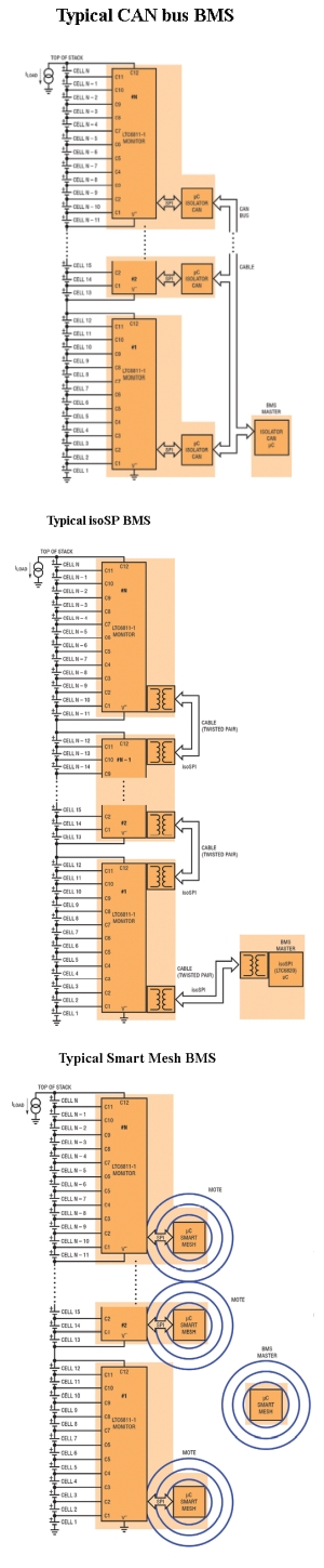
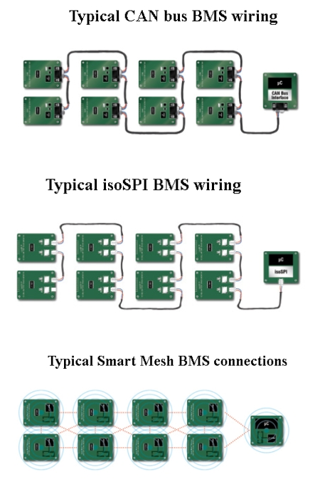
It takes a robust communication system to support a distributed, modular topology within the high electromagnetic interference (EMI) environment of an EV/HEV. Both isolated CAN Bus and Linear’s isoSPI are road-proven ways of connecting modules in this environment.
Given the success of CAN Bus in automotive applications, it provides a well-established network for interconnecting battery modules but requires several additional components. For example, implementing an isolated CAN Bus via the LTC6811 SPI interface requires the addition of a CAN transceiver, a microprocessor, and an isolator. The primary downside of a CAN Bus is the added cost and board space required for these additional elements.
An alternative to a CAN Bus interface is Linear Technology’s innovative two-wire isoSPI interface. Integrated into every LTC6811, the isoSPI interface uses a simple transformer and a single twisted pair, as opposed to the four wires required by CAN bus. The isoSPI interface provides a high RF noise-tolerant interface in which modules can connect in a daisy-chain over long cables and operate at data rates up to 1 Mbps.
One relatively new development is that of a wireless BMS. Here, each module connects with the BMS via a wireless link instead of a CAN bus cable or an isoSPI twisted pair.
Linear Technology has installed a wireless BMS in a concept car. This wireless BMS concept car is a BMW i3 that combines an LTC6811 battery stack monitor with Linear’s SmartMesh wireless mesh networking products. This demonstration of a fully wireless BMS car offers the potential for better reliability, lower cost and reduced wiring complexity for large multicell battery stacks in electric and hybrid/electric vehicles.
Automakers are challenged to assure the driving public that electric and hybrid/electric vehicles are both safe and reliable. Linear Technology is now looking beyond the safety and reliability of the battery monitoring IC to address the potential mechanical failure of connectors, cables and wiring harnesses in high-vibration automotive environments.
Many have viewed the vehicle environment characterized by a lot of metal and high EMI as too harsh for reliable operation of wireless systems. However, SmartMesh networking offers a truly redundant interconnect system that overcomes these difficulties. It uses both path and frequency diversity to route wireless messages around obstacles and to mitigate interference. Field-proven in industrial Internet-of-Things applications, SmartMesh embedded wireless networks deliver 99.999% reliable data transmission in such harsh environments as rail-car monitoring, mining, and industrial process plants. By delivering the reliability of wires while eliminating mechanical connector failures, the wireless BMS concept car shows how wireless technology can significantly improve overall system reliability and simplify the design of automotive battery management systems.
A BMS with a SmartMesh network can potentially deliver new functions that wired systems cannot. The wireless mesh network lets battery modules sit in hard-to-reach locations and makes it possible to install sensors in places where a wiring harness can’t go.
The BMS Master can collect additional data germane to the accuracy of battery SOC calculations, such as current and temperature, simply by adding SmartMesh-enabled sensors. SmartMesh automatically time-synchronizes each node to within a few microseconds and accurately time-stamps measurements at each node. The ability to time-correlate measurements taken at different locations in a vehicle is a powerful feature for accurately calculating the battery SOC and state of health (SOH). A SmartMesh node with local processing at each module improves normal BMS operation and also presents the potential for smart battery modules where module diagnostics and communication may augment assembly and service.
SmartMesh wireless sensor networking products are chips and pre-certified PCB modules complete with mesh networking software, enabling sensors to communicate in tough industrial Internet of Things (IoT) environments. There are over 50,000 of these customer networks deployed in 120 countries. These chips and modules have security measures that include NIST-certified AES128 encryption.
Leave a Reply