
by Lee Teschler, Executive Editor
Only consumers who are deeply committed to managing a lightbulb on their smart phone are likely to persevere through the lengthy setup we endured while examining the Osram Lightify LED.
The Internet of Things has arrived and it looks like an LED bulb with Wi-Fi slapped on.
In an effort to see how household items such as light bulbs might become part of the IoT, we recently dissected a Lightify smart-connected LED bulb and gateway made by Osram Sylvania Inc. Surprisingly, we found the most difficult part of the analysis was the setup procedure required to put the bulb on a Wi-Fi network. We also discovered that the way Osram approached adding wireless capabilities to this lightbulb seemed to be a little like grafting an F-35a fighter onto the airframe of a Nieuport 11 from WWI.
We pity the naïve consumer who buys one of these bulbs expecting to have it up and running in a few minutes. The installation process has the feel of something that requires an IT staff. It is lengthy. It begins with downloading a smartphone app, setting up a password-enabled account (Who knew you would have to do this for lightbulbs?), scanning in a barcode from the gateway, responding to a message sent to your email account, entering an enabling code, giving the Lightify gateway the password to your household Wi-Fi, and waiting for protracted downloads of firmware updates for the light itself and for the gateway. (Done while having to endure entreaties from the app to “sit back and relax.”)
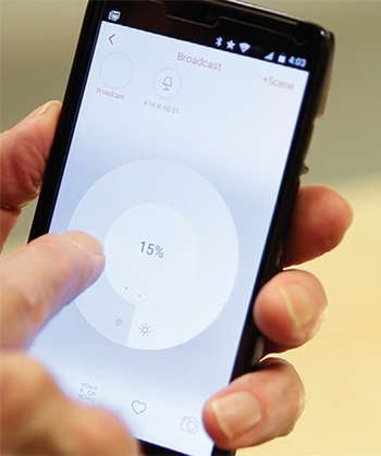
To make matters slightly worse, the smartphone app is buggy and not intuitive to operate. The only way we could get it back on track after the firmware downloads was to power-down the phone and restart.
This tedious procedure can occupy most of an hour. Consumers willing to persevere through the whole thing get a 60-W-equivalent LED bulb they can dim and put on a time schedule from their smart phone, and whose color temperature they can adjust to provide a range of white light. But we think a significant portion of those who buy this LED bulb will lose their enthusiasm for IoT appliances before they ever get the bulb to turn on.
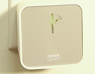
We also suspect it will come as a shock for many consumers to find that smart LED bulbs need a special gateway device to connect with household Wi-Fi. Thus the first purchase of a smart LED bulb must include the separate gateway, which looks a little like an external power supply that plugs into a wall socket. The gateway is necessary because LED bulbs are actually on their own wireless network. The gateway provides the link from the bulb network to Wi-Fi. The combination LED bulb-and-gateway will set consumers back a little less than $50. A smart LED bulb alone goes for half that, pricey compared to an ordinary dimmable LED bulb.
It should be said that up to 50 Lightify devices can work with a single gateway. But we think the prospect of going through a subset of the configuration procedure 49 more times is not likely to be appetizing to most consumers.
On a positive note, the wireless network run by the Lightify gateway seems to be relatively secure. We tried unsuccessfully to break in using a few well-known hacking techniques. The fact that the device runs a protocol that isn’t widely known is a plus from a security standpoint; Lightify networks are probably resistant to fiddling from most enterprising 15-year-olds.
Inside the LED bulb
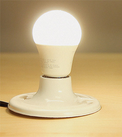
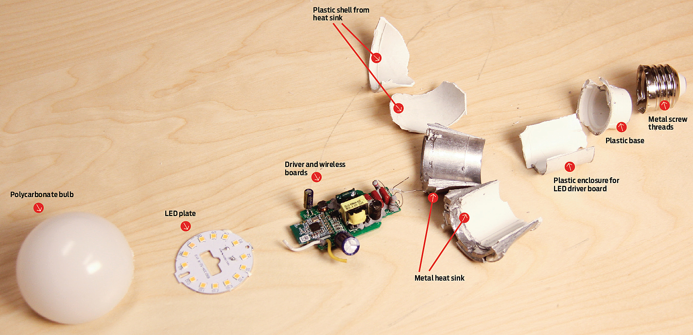
The LED bulb itself looks as though the designers started with an existing LED bulb and driver circuit, then just slapped on a PCB to add a wireless capability. The mechanical design approach is one we’ve seen in several brands of LED bulbs. It incorporates a 1.2-oz. metal heat sink to which mounts a metal plate holding the LEDs. The PCB holding the driver electronics is potted into the bulb base, and the potting material provides some structural rigidity for the connection to the metal screw-in sleeve and electrical contact. The PCB sits in a plastic sleeve that extends from the base and over the metal heat sink.

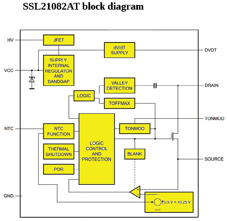
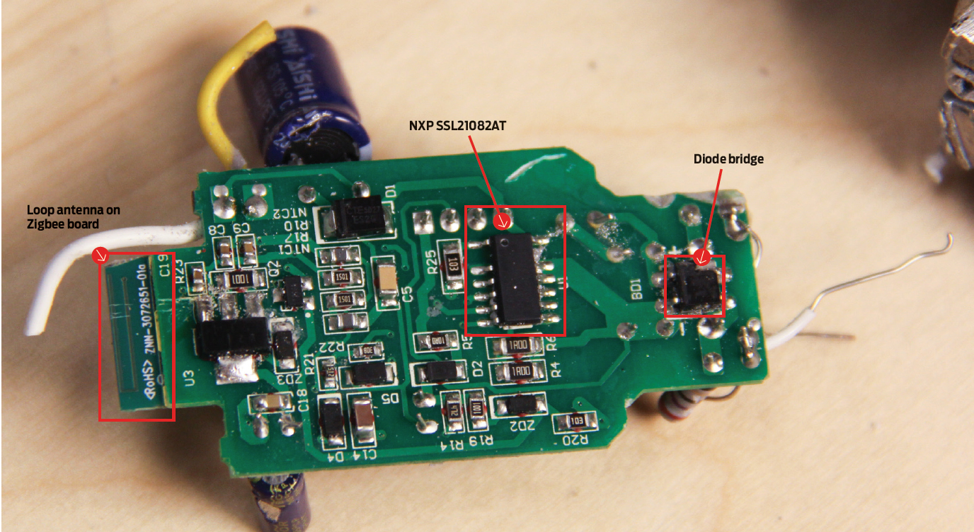
The driver circuit is based around an SSL21082AT dimmable LED driver IC from NXP. This switching power supply IC operates as a buck (step-down) converter in boundary conduction mode (BCM). BCM refers to an operation mode where the output inductor current is zero for a small period of time during each cycle, allowing the circuit to use smaller magnet components and inexpensive switching diodes.
Though the IC in the bulb allows dimming of the LED, its built-in dimming function clearly won’t play a part in the actual dimming of the bulb via wireless commands. That’s because dimmable LED drivers examine the ac waveform to decide how much to dim the LED. Thus they assume there is a triac dimmer at the light switch, which is notching out part of the ac waveform. They examine the incoming ac wave to determine the phase angle of the notching, then adjust the current to the LED accordingly.
But that’s not what happens when the dimming is commanded by a smartphone app. The ac waveform at the bulb is unaffected – it remains a full sine wave. Instead, the wireless interface adjusts the pulse-width modulation of the switching IC to deliver the amount of light that the app commands. LED light output mostly has a direct proportionality to diode current, so dimming amounts to an adjustment of the LED current.
Dimming seems to take place by means of a connection to a pin labeled NTC on the SSL21082AT chip. Though the NTC pin is normally for LED thermal protection, it can be used as an input to disable/enable light output using a digital signal (PWM dimming). Thus it is likely the bulb’s Zigbee radio uses it to dim the bulb. The bulb’s on time can be adjusted through connections to another pin on the SSL21082AT called TONMOD. It’s likely the Zigbee radio manipulates this input as well for dimming or adjustments of bulb color temperature.

The bulb can be adjusted from a warm 2700 K color temperature up to a 6500 K cool white color level at any dimness level. How it manages this is a bit of a mystery, at least to us. Other LED bulbs that boast of color-changing abilities adopt strategies such as using two kinds of LEDs with differing color temperatures, or incorporating filters that mechanically rotate over top of the LEDs to change the color output. The Osram bulb doesn’t do any of this.
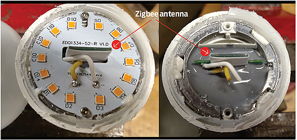
A quick look at the 14 LEDs on the Osram bulb reveals they are all wired in series. So they all energize when the bulb is on, regardless of the desired color temperature. And they all appear to be the same type.
These facts seem to eliminate the more usual methods of varying LED bulb color temperature. So we really can’t definitively pinpoint Osram’s approach to delivering a settable color temperature. However, a key point to note is that the color of LED light is sensitive to heat. And heating in LEDs is sensitive to the width of the pulse-width-modulated currents driving the LED. So we might speculate that one possible way of adjusting LED color temperature might involve the judicious modification of current pulse times.
A final point on the adjustable color temperature is that Osram makes its own LEDs, not just the bulb the LEDs sit in. So it’s possible the company has devised special devices able to change color temperature in response to some electrical parameter that isn’t widely known. If so, this would be a noteworthy development.
Making connections
The network connections for the Osram bulb are made via circuitry on a separate circuit board. This PCB has the look of something retrofitted onto an existing bulb design. It evidently was assembled separately and perhaps at a different vendor than that of the bulb itself. We say this because the main bulb PCB looks as though it may contain components that were hand-soldered to the board. And some of the solder joints don’t look particularly good.
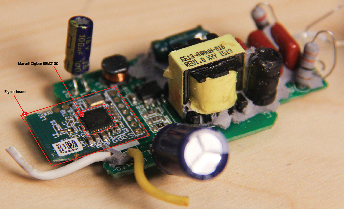
In contrast, the network PCB contains super-fine traces that are impossible to hand solder; the board material itself seems to be of a higher quality than that of the bulb. The higher quality may be necessitated by the fact that the PCB incorporates a printed antenna.
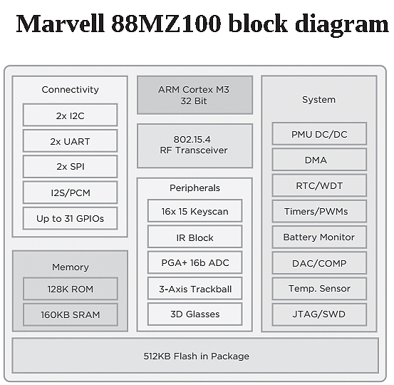
The network board protrudes out of a hole cut in the metal plate holding the LEDs. The portion of the PCB that sticks out of the hole contains a printed loop antenna. The main chip on this network board is a Marvell ZigBee 88MZ100 system-on-chip. The Zigbee networks the chip handles work in the 2.4GHz ISM band. The 88MZ100 basically combines four separate chips: a ZigBee IEEE802.15.4-2003/2006 transceiver, a 32-bit ARM Cortex M3 microcontroller, a dc-dc converter designed to take inputs from batteries ranging 2 to 3.6 V, and a 512KB serial flash.
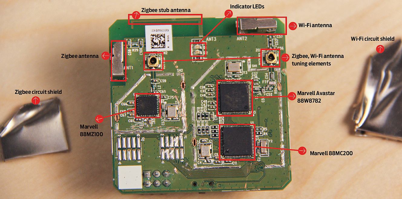
The gateway device with which the bulb communicates contains four ICs. One is the Marvell Avastar 88W8782 SoC, which is basically a WLAN on-a-chip. It is the device through which the gateway connects to your household Wi-Fi.
This Marvell chip provides the combined functions of Direct Sequence Spread Spectrum (DSSS) and Orthogonal Frequency Division Multiplexing (OFDM) baseband modulation, Medium Access Controller (MAC), host interfaces, and direct-conversion WLAN RF radio. For security, the chip implements widely used encryption methods that include Advanced Encryption Standard (AES)/Counter Mode CBC-MAC Protocol (CCMP), Wired Equivalent Privacy (WEP) with Temporal Key Integrity Protocol (TKIP), and others.
The WLAN chip sits on the PCB inside the same metal shield as a Marvell 88MC200 microcontroller. This is another SoC incorporating 512KB SRAM memory, 8MB of on-chip serial flash memory, a DAC module with 10-bit resolution, and I/O interfaces. It includes eight channels of Direct Memory Access (DMA) as well as a watchdog timer that can generate a reset or an interrupt when it times out. Four UART devices integrated in the chip.
In a second separate shielded area of the PCB sits a Marvell 88MZ100 ZigBee microcontroller system-on-chip (SoC). This, of course, is the controller handling the Zigbee network containing the LED lightbulb and whatever else is networked in.
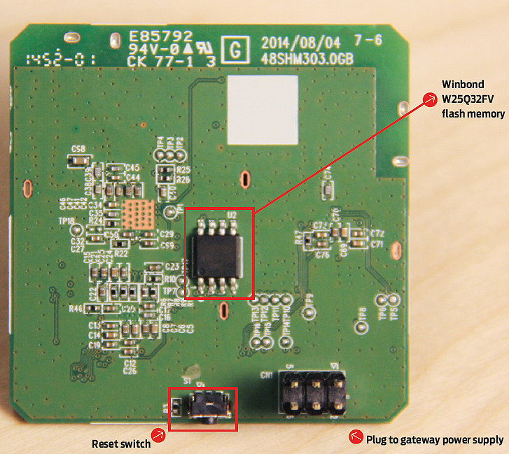
The fourth chip on the board is a W25Q32FV (32M-bit) Serial Flash memory from Winbond Electronics Corp. It sits by itself on the reverse side of the board.
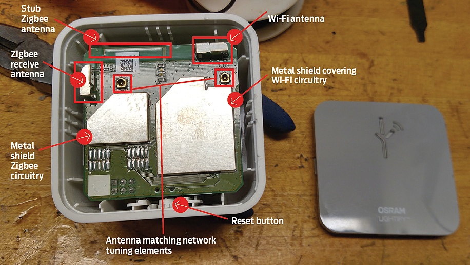
There are a couple points to note on the gateway board. It seems to contain three antennas. One is printed on the circuit board and looks to be a stub antenna. Its length is about that of a quarter-wave for the 915 MHz Zigbee band. Our guess is that it handles RF transmissions to the Zigbee devices on the network.
The other two antennas are oddly shaped considering they are meant to detect electromagnetic energy in the ISM band. They are rectangular metal clip-like shapes that are soldered to the PCB. One seems to connect to the Zigbee transceiver, the other to the Wi-Fi circuit. Both are in series with devices that seem to be variable capacitors, likely put there to match antenna impedance to the input impedance of the Wi-Fi and Zigbee radios. The fact that Osram was compelled to add a variable tuning element to the antenna circuit may indicate the two metal clips don’t make particularly good ISM-band antennas.
All in all, the Osram Lightify bulb is interesting IoT technology. Too bad it involves a tedious set-up for anyone who isn’t a one-percenter able to hire personalized IT help.
References
Marvell Technology Group Ltd.
www.marvell.com
NXP Semiconductors
www.nxp.com
Osram Sylvania Inc.
www.sylvania.com
Identical in every way to the GE Link bulbs and Quirky Link Hub. You can pull the flash off and dump the node.js code on the Link Hub, wonder what difference there is to the code on the Osram hub.
Should have seen the mess of crystalized flux left on the Link Hub board, was horrible.
Actually, one difference I see is the packaging of the hub. The Link Hub case is a mirror of the Osram. Rather than the front plate coming off, the plate portion is the plug side and the majority of the case comes off to expose both boards.
Also the silkscreening on the back, it is dated 2014/10/08 48SHM303.OGC <— C not B and there are a few additional traces. Other than that same radios, same layout.
The GE Link lights also make the antenna a feature of the light, displaying it proudly in the middle of a clear beam spreading lens. It is stuck in all that horrible silicone as well. Wired up the radio can be used by itself with a 3.3V power supply to trigger a relay or control something via the PWM output normally sent to the light.
Haven't dug around too much (how I stumbled here) but am looking for the pinout of the 88MZ100 chip to see about accessing the programming within to repurpose the zigbee radio. Have a bunch of these lights I got for $5 after the company (Quirky) went belly up leaving GE with a hub that no longer receives support or updates. I've read they are in talks for buying the firmware, but that has yet to be seen. Until then I dumped a copy of the Winbond chip and all the hub webserver stuff is in there and it is pretty generic. The work quirky appears 3 times, Line 6 and 17 of zigbee.html and line 4 of index.html however the header title is "Marvell Provisioning". Uses jquery for all the functions. /*! jQuery Mobile 1.3.1 | Git HEAD hash: 74b4bec 2013-04-10T21:57:23Z | (c) 2010, 2013 jQuery Foundation, Inc. | jquery.org/license */
This method that OSRAM is doing with one led producing more than one color temp is interesting. Actually smae thing is in the LIGHTIFY rgbw lamps. I craked one of those open and it turned out that there was only three different type of leds. Red,Blue and Green/white. So Warm white was done just by powering the green/white led and any cooler colors are done with green/white + blue led. Would be nice to hear from OSRAM what type of led is that one that changes color with two terminals.