
Here are a few tips for selecting resistors that will accurately gauge current.
Bert Weiss, Rutronik Elektronische Bauelemente GmbH
Today, practically every control and monitoring circuit uses shunt-based current measurements as an alternative to sensors. To make these measurements accurately, it is useful to understand how shunts work. Because the method is categorized as a precision measuring technology, it should not be regarded as trivial.
A shunt is a low-value resistor used to measure current – it is therefore also referred to as a current-sense resistor. The shunt typically connects in series so it carries the current of interest. A voltage measurement device then connects in parallel with the shunt. The current through the shunt generates a voltage drop that is measured. The current value is derived from Ohm’s law and the known resistance (I = V/R). To keep power loss – and thus heat development – to a minimum, shunts must have resistive values no higher than the milliohm range. Some are even below that.
The advantage of this measuring method is that it allows the quick detection and elimination of faults. Shunts are therefore particularly interesting for safety-relevant applications where faults must be detected. Furthermore, shunts deliver precise measurements and thus enable the efficient control of drives or the monitoring of battery management systems. And shunt resistors are an excellent value for money.
Shunts are basically suitable for any type of measuring application – be it direct or alternating current. Shunts are currently experiencing a boom, especially thanks to the rising number of condition measurements in vehicles — engine and battery management, airbag control units, ABS, infotainment systems, and so forth. Current-sense resistors are also becoming ever more widely used in industrial applications, medical technology, for regenerative energies, and for smart metering.

Shunts are available as metal layer technology and in full-metal versions. Layer resistors are considerably less expensive but their resistance value changes with temperature to a greater degree than do the full-metal devices.
The make-up of metal-layer shunts also brings a notable disadvantage: With metal layer resistors, a paste is applied to a ceramic substrate and adjusted to the desired value using laser trimming. This results in an inhomogeneous structure that is trimmed to the rated value as a meandering shape. This meandering shape causes a series inductance, potentially degrading current measurements. The voltage drop at the shunt, U, then follows the equation U = I x R – L(di/dt). Consequently, metal layer resistors are only worth considering if inductance is unimportant.

Full-metal shunt resistors consist of a homogeneous resistive element so that no additional inductance develops. This quality is key in such high-precision applications as medical technology or precision measurement devices. Furthermore, these resistors are characterized by high measurement accuracy and resistance to thermal shock. They are available in various sizes – including versions that are much larger than standard chip resistors – and TK-values way below 100 ppm/K. Full-metal resistors can operate with an output of up to 7 W at maximum temperatures of 275°C. They can have resistive values up to the low single-digit milliohm range.
The optimum resistive value can be determined quite easily: The lowest measuring voltage that still gives sufficiently accurate results is divided by the lowest current value of the measuring range.
There is a trend toward smaller shunts with higher outputs; also in wider use are customer-specific versions with special connection geometries and sizes. As shunt resistors are relatively expensive compared to other resistor technologies, they are available in small batch sizes and test samples.
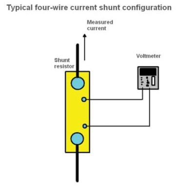
Some shunts have four wires. Here, the current flows through two connections and the voltage is measured at the other two. The voltage drop at the resistors can be determined using the internal Kelvin connections, so the resulting measuring errors can be eliminated.
Four-wire shunts are used in two scenarios: First, when the line and contact resistance are relatively high and, in contrast to the measured resistance, not negligible. Second, when the resistive value is below 10 mΩ. Because the resistive values of the conductors are also in the milliohm range, they must thus be accounted for.
The method you have described for measuring current is not the method of using a shunt resistor. It is an alternative method, and should be described as such, so as not to foster confusion.