
Measuring the voltage drop across a current-sense resistor can be a trivial issue or a challenging one depending on the rail voltage and other factors.
In previous articles, we looked at an apparently simple issue of sizing the resistor used for this common technique for current sensing (EE World Content References 1 and 2). This FAQ looks at the complementary issue of accurately, reliably, and even safely measuring the voltage across that resistor.
Q: Is a resistor my only choice for current sensing?
A: Not at all. Alternatives include Hall-effect devices and magnetic pickup coils. Each option offers relative pros and cons in a given application, and these pros and cons change and change as the voltage, current, and other technical factors shift. The References discuss some of these tradeoffs, but keep in mind that some of these references are from vendors of a specific solution, so they may be somewhat biased. Nevertheless, they are worth reading if you want to explore the various alternatives.
Q: Will this article look at using those other sensing techniques?
A: Not here, sorry. Instead, we will assume the decision has been made to use a resistor for a variety of reasons. This is a widely used approach as it offers a good combination of accuracy, ease of interfacing, and other attributes – but, again, it has some design conditions and concerns that need to be understood.
Q: What’s the basic topology?
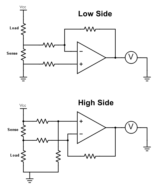
A: As noted before, the first issue is whether to use high-side or low-side sensing (Figure 1). Low-side sensing is much easier to interface with and read the voltage drop across the resistor. However, it also brings some serious system drawbacks as the lower side of the load is no longer grounded (or connected to circuit common). There are standard topologies such as the half-bridge or full-bridge where the load itself is not grounded, so it is inherently a high-side situation.
Q: What’s the big deal about sensing a voltage across a resistor? Shouldn’t a basic op amp as amplifier be able to do it?
A: It’s not a big deal in principle, but it may be in practice. For low-side sensing, one side of the sensing amplifier is connected to ground (or common) just as the load is, and all that the op amp has to do is sense and amplify the voltage across that resistor, which is typically about 100 mV.
Q: Then what’s the special problem with high-side sensing?
A: One major problem is summarized by the parameter called common-mode voltage (CMV). Looking at the schematic diagram, you’ll see that while the voltage across the resistor – the potential difference – is low, the resistor’s upper end is at the rail voltage, and the lower end is just slightly below it. In other words, you have a small potential difference riding on top of a much-higher voltage, which is common to both sides (note that the word “common” as used here is not the same as a circuit’s “common” connection point or reference).
Q: How large is that common voltage?
A: It’s entirely a function of the rail voltage in the system. For a small, battery-powered design, it may only be a few volts; in other cases, it may be hundreds of volts or more. Again, the biggest virtue of low-side sensing is that there is no CMV, but its system-level negatives outweigh that benefit.
Q: So, what’s the problem with higher CMVs?
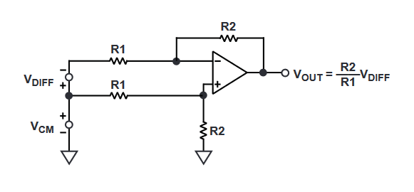
A: It’s this: the op amp which is sensing the differential voltage across the resistor is also connected to ground (common) as a necessary part of its design even as it is sensing that small voltage in the presence of the CMV (Figure 2). In general, amplifiers cannot do that well or without damage once the CMV gets larger and exceeds the amplifier’s CMV limit. A typical op amp designed for sensing the differential voltage across the resistor can tolerate a maximum CMV of 30 to 50 V.
Q: Aren’t there amplifiers that are designed to handle small differences despite larger CMVs?
A: Yes, there are, and they come in various configurations such as difference amplifiers or current-sense amplifiers (more on these later). Even so, there are limits as to how much CMV they can handle or how well they will perform in the presence of larger CMVs.
Q: But my design uses a low-voltage rail, under 10 V, so do I still have a problem?
A: Probably not, and that’s why the sense resistor and amplifier combination is so widely used at these lower voltages.
Q: My design uses a rail of around 75 V. Can’t I just get an amplifier with a CMV rating above that value so I won’t have a problem?
A: Yes and no. While the amplifier may tolerate the CMV without a problem, it also means the amplifier sees that high potential difference with respect to ground (common). Therefore, the CMV is also present at the amplifier and associated circuitry, and there’s a need to ensure that the high voltage does not “touch” other circuit components which that higher voltage may damage.
Q: Is that all?
A: No: equally important, it becomes a possible user-safety issue, as the higher voltages are subject to regulatory mandates. Depending on the end application and regulatory agency, voltages above about 50 to 60 V are considered potentially hazardous. Thus, while the load (such as a motor) may have suitable insulation and protection so a user cannot touch any higher voltages, the associated circuit board may not – and that may not be acceptable in terms of regulatory standards.
Q: So what can be done?
A: One solution is to develop a design which keeps the entire circuit board and any presumed dangerous voltages away from users. However, this is more difficult than it may seem, especially as regulatory mandates generally very strict and may also require the means of protection (MOP) to function even if there is a failure in the installation. Therefore, a simple protection arrangement may not be enough, and it can take a complicated solution to get the required approvals.
Part 2 of this article looks at galvanic isolation and its role in dealing with CMV.
Related EE World Content
- A tradeoff case study: Sizing the current-sense resistor, Part 1
- A tradeoff case study: Sizing the current-sense resistor, Part 2
- The basics of AC-line isolation for safety, Part 1: The challenge
- The basics of AC-line isolation for safety, Part 2: The solution
- Wheatstone bridge, Part 1: Principles and basic applications
- Wheatstone bridge, Part 2: Additional considerations
- Kelvin 4-Wire sensing solves the “IR Drop” problem
- Galvanic isolation for electric vehicle systems
- High-voltage gate driver with 6-kV galvanic isolation comes in compact package
- Super-accurate 400-kHz current sensor carries 5-kV isolation rating
- High-power current shunt modules feature 1.5-kV isolation
- One-watt dc/dc converter carries 5-kVac reinforced isolation
- Bi-directional current sense amp targets full-scale direct motor-winding current measurements
- Power/energy monitor includes sense resistor to handle ±65 A
External References (these are just a few of the many available ones; current sensing via a resistor or other means is a very important and widely discussed topic)
- Texas Instruments, “Six ways to sense current and how to decide which to use”
- Texas Instruments, SBAA293B, “Comparing shunt-and hall-based isolated current-sensing solutions in HEV/EV”
- Texas Instruments, SBAA359A, “Comparing Isolated Amplifiers and Isolated Modulators”
- Analog Devices, MT-041, “Op Amp Input and Output Common-Mode and Differential Voltage Range”
- Analog Devices, “Finding the Needle in a Haystack: Measuring small differential voltages in the presence of large common-mode voltages”
- Analog Devices, MT-068, “Difference and Current Sense Amplifiers”
- Maxim Integrated, Tutorial 2045, “Understanding Common-Mode Signals”
- TT Electronics. “Using Current Sense Resistors to Improve Efficiency”
- Knick Interface LLC, “Shunt Resistor versus Hall Effect Technology” (focused on fairly high currents)
- Homemade Circuit Project, “Precision Current Sensing and Monitoring Circuit”

Leave a Reply