
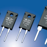
Measuring the voltage drop across a current-sense resistor can be a trivial issue or a challenging one depending on the rail voltage and other factors.
The problem with low-side sensing is that it “ungrounds” the load, and the alternative is high-side sensing. This part looks at the use of isolation to deal with CMV and associated safety issues.
Q: What is the alternative to providing extra insulation and protection against higher voltages?
A: In a word, “isolation” is often the answer (also called galvanic isolation or ohmic isolation).
Q: What does isolation do?
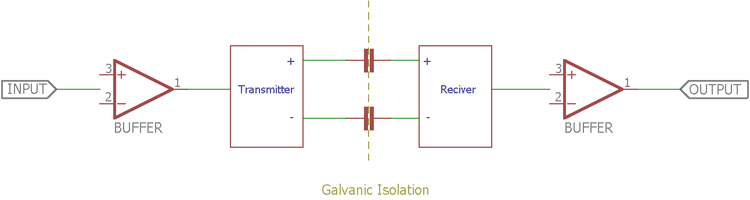
A: It allows for the desired differential signal (the voltage across the resistor) to pass on to the remaining circuitry while assuring that there is no path for the high common-mode voltage to reach that circuitry (Figure 1).
Q: Is this the same as AC-line transformer isolation?
A: The standard 50/60 Hz AC line transformer is the best-known example of isolation, as it allows the line voltage (or a stepped-up/down version of it) to pass from primary to secondary sides, yet without a conductive ohmic path between those two sides (EE World Content References 3 and 4). However, as discussed here, isolation is different in many ways than isolation for AC-line safety alone, as the issues associated with AC-line hot, neutral, and ground wires are often not “in the picture” here.
Q: How is isolation implemented?
A: Several techniques are in use: magnetic (transformer), capacitive, optical, and even RF. The details of each, and their relative attributes, are beyond the scope of this article.
Q: How much isolation is available?
A: Quite a lot, and depending on how it is achieved, most isolation techniques, which also meet regulatory standards, are rated at least 1 or 2 kV or more. These isolators also have various VDE, CSA, and UL certifications as appropriate, which makes regulatory approval of the overall design much easier.
Q: Do I only need such isolation for these higher CMVs?
A: No, there are many design situations with even a lower-voltage design well within the CMV-safety rating, which needs isolation to prevent functional – not safety – problems with different grounds or commons, or differences in voltage references between circuit blocks. It may also be needed where the sensor is not ground-referenced (just as the current-sense resistor is not ground referenced but “floats” at a CMV. Sensors and transducers in Wheatstone bridges often need isolation, for example (EE World Content References 5 and 6).
Q: I’m not doing current sensing via a resistor, so is any of this entire isolation and CMV discussion even relevant to me?
A: Actually, it is. Sensing the voltage across a resistor, which is at a high CMV, is topologically very similar to sensing the voltage across a series string of batteries or solar cells (Figure 2). Although the voltage across each battery or cell is low (on the order of a few volts), the battery (or cell) of interest will have a higher and higher CMV as you go up the series string.
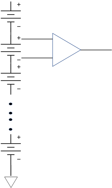
This CMV can be a problem or safety risk when you need the measure the voltage across a single battery or cell (a very commonplace scenario). As with the sense resistor, the challenge here is to measure a small voltage differential despite the CMV, regardless of whether that voltage is due to current flowing through a sense resistor or developed by a battery. A high-voltage battery pack such as in an EV or HEV can have hundreds of 2-to-3 V cells in series, so the CMV numbers do add up quickly.
The next part of this FAQ looks at various components for dealing with CMV.
Related EE World Content
- A tradeoff case study: Sizing the current-sense resistor, Part 1
- A tradeoff case study: Sizing the current-sense resistor, Part 2
- The basics of AC-line isolation for safety, Part 1: The challenge
- The basics of AC-line isolation for safety, Part 2: The solution
- Wheatstone bridge, Part 1: Principles and basic applications
- Wheatstone bridge, Part 2: Additional considerations
- Kelvin 4-Wire sensing solves the “IR Drop” problem
- Galvanic isolation for electric vehicle systems
- High-voltage gate driver with 6-kV galvanic isolation comes in compact package
- Super-accurate 400-kHz current sensor carries 5-kV isolation rating
- High-power current shunt modules feature 1.5-kV isolation
- One-watt dc/dc converter carries 5-kVac reinforced isolation
- Bi-directional current sense amp targets full-scale direct motor-winding current measurements
- Power/energy monitor includes sense resistor to handle ±65 A
External References (these are just a few of the many available ones; current sensing via a resistor or other means is a very important and widely discussed topic)
- Texas Instruments, “Six ways to sense current and how to decide which to use”
- Texas Instruments, SBAA293B, “Comparing shunt-and hall-based isolated current-sensing solutions in HEV/EV”
- Texas Instruments, SBAA359A, “Comparing Isolated Amplifiers and Isolated Modulators”
- Analog Devices, MT-041, “Op Amp Input and Output Common-Mode and Differential Voltage Range”
- Analog Devices, “Finding the Needle in a Haystack: Measuring small differential voltages in the presence of large common-mode voltages”
- Analog Devices, MT-068, “Difference and Current Sense Amplifiers”
- Maxim Integrated, Tutorial 2045, “Understanding Common-Mode Signals”
- TT Electronics. “Using Current Sense Resistors to Improve Efficiency”
- Knick Interface LLC, “Shunt Resistor versus Hall Effect Technology” (focused on fairly high currents)
- Homemade Circuit Project, “Precision Current Sensing and Monitoring Circuit”
Leave a Reply