
Measuring the voltage drop across a current-sense resistor can be a trivial issue or a challenging one depending on the rail voltage and other factors.
Part 2 of this FAQ looked at the issues related to sensing the small differential voltage across a current-sense resistor, often but not always in the presence of a high common-mode voltage. This part begins a look at techniques and components available for sensing that voltage, including the non-isolated amplifier, the isolated amplifier, and the hybrid isolated analog/digital) approach. As is usually the case, there is no single “right” solution. The best approach for a design is a balance among performance specifications, cost, frequency of load current being monitored, and other factors.
Q: Can an ordinary op amp be used for sensing the voltage?
A: Yes, a standard op amp is a possible choice, but there are some variations which are better tailored to this function, such as the difference amplifier and the current-sense amplifier. A difference amplifier attenuates high input voltages to bring the signal to a level the amplifier can tolerate. The current-sense amplifier converts the differential input voltage to a current, and then back to a ground-referenced voltage; its input amplifier can withstand large common-mode voltages due to its high-voltage manufacturing process. Deciding between the two approaches requires matching their key attributes to the application priorities.
One example of the current-sense amplifier is the Texas Instruments INA290-Q1, an ultra-precise amplifier that can measure voltage drops over a wide common-mode range of ±2.7 V to ±120 V (Figure 1). It is in a highly space-efficient SC-70 package and AEC-Q100 qualified for automotive use, and has a 1-MHz bandwidth.

Q: What if my CMV is higher?
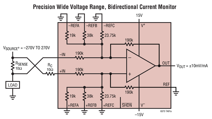
A: There are amplifiers which use specialized IC processes to handle these higher voltages. For example, the Analog Devices LT6375 is a precision voltage-difference amplifier which handles up to ±270 V CMV (Figure 2).
Q: Undoubtedly, there are many important parameters to check when selecting an amplifier for this function. Rather than go through all of them in detail, can you cite a few and identify a few key specifications?
A: In addition to the maximum CMV which the amplifier can tolerate, there is a common mode rejection ratio (CMRR). The amplifier – where a difference amplifier or current-sense amplifier – is attempting to extract a small differential signal in the presence of a large common signal. This common signal interferes with seeing that small signal. CMRR, which is always specified in dB, defines how well the amplifier can suppress the common mode signal while making the difference measurement.
CMRRs range typically ranges from 60 dB to as high as 120 dB. It is not constant over the amplifier bandwidth and generally declines as frequency increases. Thus, a specified CMRR may be adequate for low-frequency measurements up to several kHz but inadequate for looking at changes on the order of hundreds of kHz or higher. There, the CMRR is specified versus frequency on datasheets.
Other important specifications include gain error, gain drift, and offset voltage, all of which are called out by the device vendor.
The next and final part of this FAQ looks at isolation amplifiers in dealing with CMV and safety issues.
Related EE World Content
- A tradeoff case study: Sizing the current-sense resistor, Part 1
- A tradeoff case study: Sizing the current-sense resistor, Part 2
- The basics of AC-line isolation for safety, Part 1: The challenge
- The basics of AC-line isolation for safety, Part 2: The solution
- Wheatstone bridge, Part 1: Principles and basic applications
- Wheatstone bridge, Part 2: Additional considerations
- Kelvin 4-Wire sensing solves the “IR Drop” problem
- Galvanic isolation for electric vehicle systems
- High-voltage gate driver with 6-kV galvanic isolation comes in compact package
- Super-accurate 400-kHz current sensor carries 5-kV isolation rating
- High-power current shunt modules feature 1.5-kV isolation
- One-watt dc/dc converter carries 5-kVac reinforced isolation
- Bi-directional current sense amp targets full-scale direct motor-winding current measurements
- Power/energy monitor includes sense resistor to handle ±65 A
External References (these are just a few of the many available ones; current sensing via a resistor or other means is a very important and widely discussed topic)
- Texas Instruments, “Six ways to sense current and how to decide which to use”
- Texas Instruments, SBAA293B, “Comparing shunt-and hall-based isolated current-sensing solutions in HEV/EV”
- Texas Instruments, SBAA359A, “Comparing Isolated Amplifiers and Isolated Modulators”
- Analog Devices, MT-041, “Op Amp Input and Output Common-Mode and Differential Voltage Range”
- Analog Devices, “Finding the Needle in a Haystack: Measuring small differential voltages in the presence of large common-mode voltages”
- Analog Devices, MT-068, “Difference and Current Sense Amplifiers”
- Maxim Integrated, Tutorial 2045, “Understanding Common-Mode Signals”
- TT Electronics. “Using Current Sense Resistors to Improve Efficiency”
- Knick Interface LLC, “Shunt Resistor versus Hall Effect Technology” (focused on fairly high currents)
- Homemade Circuit Project, “Precision Current Sensing and Monitoring Circuit”
Leave a Reply