Even though ac power transmission dominates due to its flexibility in delivering power to end users, dc power transmission has been used to send higher power levels over longer distances for over a century. The earliest high-voltage DC (HVDC) power transmission systems, starting in the 1890s and continuing through the 1930s, used motor-generators’ Thury system. Second-generation HVDC designs used mercury-arc valves. Third-generation designs employed various types of solid-state thyristors, and the newest designs use IGBTs.
Today, most HVDC links use voltages between 100kV and 800kV. A few ultra-high-voltage DC (UHVDC) links employ 1,000kV and more and can deliver 12GW over a distance of 3,300km. Compared with today’s advanced technologies, HVDC had a humble beginning.
Electromechanical HVDC systems
The first long-distance transmission of electric power was demonstrated using direct current in 1882 at Miesbach-Munich Power Transmission, but only 2.5kW was transmitted over 57km using 2,000 Vdc. A simple iron telegraph wire was used to carry the 1.25 Amps of current. The system operated a few days before failing. In 1885 a more robust system was built to supply Bözingen, Germany (a municipality now part of Biel/Bienne) with 30kW of power generated from nearby Taubenlochschlucht gorge using 500 Vdc transmission.
René Thury was the key pioneer in the development of early HVDC systems. Thury used generators in series to attain high transmission voltages, he solved the commutation problems, and he built the first dynamos with voltages of up to 25kV. He also developed the Thury control system, which was used to regulate the power plant’s voltage. In a Thury, system current is kept constant, and when increasing load demands more power, the voltage is increased.
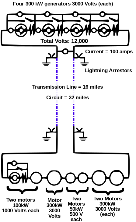
The Thury system’s primary limitation was the series architecture, which meant greater opportunity for power failures. Placing loads in series means that since current must flow through each device to get to the next, if the circuit is broken in any of the devices, the current stops at all other loads. The use of the Thury system was limited to delivering a few megawatts. The maximum transmission voltage for Thury systems was about 150kV, but most were operated at voltages under 100kV.

Grid-controlled mercury arc valves
The development of grid-controlled mercury arc valves enabled the use of HVDC for larger transmission projects. But it took several decades of development before mercury arc valves were ready for use in HVDC systems. The basic mercury arc rectifier was invented in 1902 by Peter Cooper Hewitt. Installation of a control grid between the anode and the pool cathode was first suggested in 1914. The grid allows control of the valve’s conduction, which controls the average output voltage produced by the rectifier. The start of the current flow can be delayed past when the arc would form in an uncontrolled valve.
Gird-controlled mercury arc valve technology for DC power transmission was under active development from about 1920 to 1940. For example, in 1932, General Electric tested mercury-vapor valves and a 12kV DC transmission line, which also served to convert 40Hz generation to serve 60Hz loads, at Mechanicville, New York.
Dr. August Uno Lamm was one of the pioneer developers of mercury-vapor valves. In 1929 he was made manager of the project to develop a high-voltage mercury arc valve at ASEA. Valves at the time operated only up to about 2500 volts. It was understood that if higher-voltage valves were available, they could have a practical use to transmit large quantities of electric energy over long distances.
In 1943 Lamm obtained his Ph.D. from the Royal Institute of Technology, studying part-time while developing the mercury arc valve. After about twenty years of development work to produce a mercury arc valve with the necessary rating for HVDC transmission, ASEA obtained a contract for the 20MW, 100kV HVDC Gotland project in 1950, when completed in 1955, became the first modern commercial HVDC system. Eventually, Dr. Lamm was instrumental in developing grid-controlled mercury arc valves with voltage ratings of 150kV.
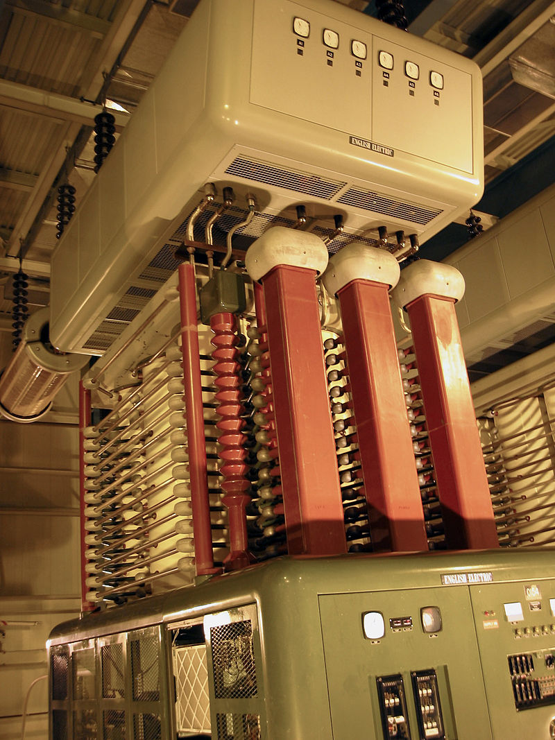
Mercury arc valves have tall porcelain columns for the anode connection and a steel tank at the cathode potential. The tall porcelain column required for the anode connections is more difficult to cool than the cathode steel tank. Thermal considerations limit the usable current rating to about 200 to 300 A per anode. As a result, mercury-arc valves for HVDC are often constructed with four or six anode columns in parallel. The anode columns are air-cooled, while the cathode tanks can be either water-cooled or air-cooled. Between 1954 and 1972, mercury arc valves were common in HVDC system designs.
Mercury arc valves require an external circuit to force the current to zero and thus turn off the valve. In HVDC applications, the AC power system itself provides the means of commutating the current to another valve in the converter. Consequently, converters built with mercury arc valves are known as line-commutated converters (LCC). LCCs require rotating synchronous machines in the AC systems to which they are connected, making power transmission into a passive load impractical. Beginning in 1972, thyristors started replacing mercury arc valves in HVDC systems.
Thyristors and the beginning of modern HVDC systems
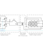
The main parts of a modern HVDC system are the HVDC converter stations and the interconnecting transmission lines. The HVDC converter can employ thyristors of various types or IGBTs as the main power switching elements. When they were first introduced into HVDC applications in the 1970s, thyristors were simply used to replace the LCC converters’ mercury-arc valves. That resulted in more compact and reliable systems. Later, gate-turn-off (GTO) thyristors and IGBTs were introduced that enabled higher performance voltage-sourced converters (VSCs). Almost all the power converters in an HVDC system are bidirectional. In one direction, they operate as rectifiers; in the opposite direction, they become inverters. The converters are housed in a building called a valve hall.
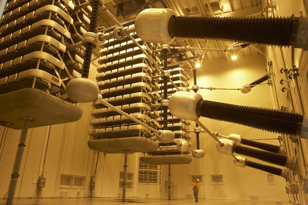
LCC converters continue to be used where very high capacity and efficiency are required. VSC converters are the faster-growing design and are used for smaller installations and for connecting renewable energy resources, especially large-scale wind farms, to the grid. In addition, the introduction of IGBTs has enabled the development of multi-level HVDC power converters. Multi-level converters enable the use of HVDC in smaller installations than was previously economically justifiable.
An HVDC converter station is a specialized type of substation that includes three-phase AC switchgear, transformers, capacitors to control reactive power, filters for harmonic control, and the HVDC converter switchgear.
The DC equipment typically includes one or more coils to add smoothing inductance to the line. These inductors can range from 0.1H to 1.0H. In addition, high-frequency filters are often added, especially if the transmission cables will be used for power line communications (PLC) for communication and control or if an overhead line will be placed in populated areas.
The converter transformers operate with 12 pulses for each cycle in the AC supply, eliminating numerous harmonic current components. The insulation of the transformer windings must be able to withstand a large DC potential to earth. Proper transformer insulation can be a major design challenge. With today’s technology, it is not practical to build transformers larger than about 300MVA. If more power is needed, several transformers are connected.
When LCC power conversion is used, banks of switched capacitors are often used to provide the reactive power needed to control the converters. The use of VSC power conversion, where the converters can absorb reactive and real power, eliminates the need for the capacitor banks. Harmonic filters are used to eliminate harmonic noise on the lines and provide reactive power in LCC converter stations. VSC station designs produce fewer harmonics compared with LCC designs, and the harmonic filters are smaller and can even be eliminated in some designs. Finally, HVDC converter stations need AC switchgear similar to that found in a conventional substation.
As seen, improvements in HVDC technology have generally been driven by advancements in power components. The next article in this three-part FAQ series will look into HVDC converters, components, and control systems. The third FAQ will consider HVDC transmission system architectures and use cases.
References:
High-voltage direct current, Wikipedia
Mercury-arc valve, Wikipedia
René Thury, Wikipedia
The history of high voltage direct current transmission, Australian Journal of Multi-disciplinary Engineering



Leave a Reply